Hey, real quick! We’ve been cutting scarf fixes for enormous post feet, and fitting teleport pads for octagonal lanterns. Updates on Chestnut St Lantern, Brasen Hill Barn, and Jennison Barn, below.
Teleport Pad, Photo by Jacob Imlay
Chestnut St Church Lantern, Camden, ME: This cute little lantern was cut and fit at the shop, and is ready for transport to the Lyman-Morse boat shop later this week. There it will be fit with a 50-foot fiberglass spire and four 7-foot half-round hoods. Jake laid out the frame and Tim, Zach and Charlie cut and fit the joinery. Zach’s experience building guitars and Tim’s experience making furniture helped maintain tight tolerances. The entire lantern and spire will be laid down on a low-riding flatbed for final transport to the church, where a crane will tip the entire assembly up vertical. It is important that the joinery is tight in order to withstand the torque and lateral loads. Scott, Tim and Arron worked with Taylor-made builders up in Camden to plumb the tower and repair the belfry post feet at the Chestnut St Church. More about removing the old spire, here.
Lady Lantern, photo by Jacob Imlay
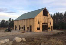
Brasen Hill Barn, Barrington, NH: Led by Dave and Dan, the rest of the crew have been busy with an enormous barn restoration at Brazen Hill Farm. The barn is beautifully hewn, with drive posts like tree trunks. The deterioration was extensive and the barn was completely dismantled for repairs. The extent of rot meant that the barn was heavily braced and was disassembled piece by piece by a crew of eight over two days.
Brasen Barn from above, photo by Josh McNally
Dave, Dan, Tom, Byam and Michael have been busy making traditional timber frame repairs at our shop in Nottingham, NH. Given the extent of damage, the crew worked hard to preserve any viable original material. That means a lot of dutchman and post feet fixes. Dan Boyle documented the repair and fitting process. A few of his process photos, below.
Undersquinted face fix, photo by Dan Boyle
An under-squinted dutchman repair can be used to repair the cheek of a mortise where a pin has blown out the relish. The rest of the post was in good condition and of a dimension and quality that is difficult (but not impossible) to find today.
Get (in the) Bent Brian, photo by Dan Boyle
After the rotten timbers are repaired or reproduced, we use come-alongs to pull the joinery tight and the bent square. Then we drill holes for the 1-inch oak pins that will hold the joinery together.
Eave fitting, photo by Dan Boyle
The barn is big, almost 70-feet long and 40-feet wide. It contains seven bents. The finished frame was raised almost a month ago, and Dave and Scott documented the process by helmet-cam. Stay tuned for the movie.
Jennison Barn, photo by Josh McNally
Jennison Barn, Lee, NH: New Hampshire Preservation Alliance has featured the Jennison Barn as one of their 52 barns in 52 weeks. The NHPA article captures why preservation is important on a human scale, from families to communities. Read their story, here.
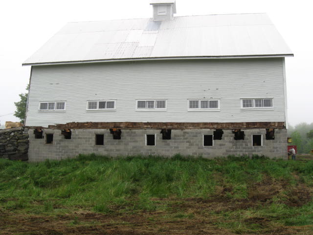
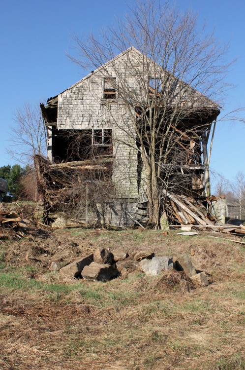
I write a lot about our unusual jobs: a deserted island, an elevated dance floor, or a building-sized jewelry box, but most of us got into this to do jobs like the Jennison barn. The job incorporates so many of PTF’s defining motifs: barn preservation, adaptive re-use, local history and creative clients. The Jennisons called in early 2015 about a barn that had collapsed under extreme snow loads. After assessing the damage to the frame, and a long period of negotiation with the insurance company, we concluded that the barn was not salvageable, and that its replacement would need to be significantly scaled down. Ultimately, too many of the posts had snapped in the collapse, and the replacement coverage did not include the embodied value of the craftmanship and timber joinery. Fortunately, PTF had dismantled a smaller frame the previous year, and had hoped we could find it a home nearby.
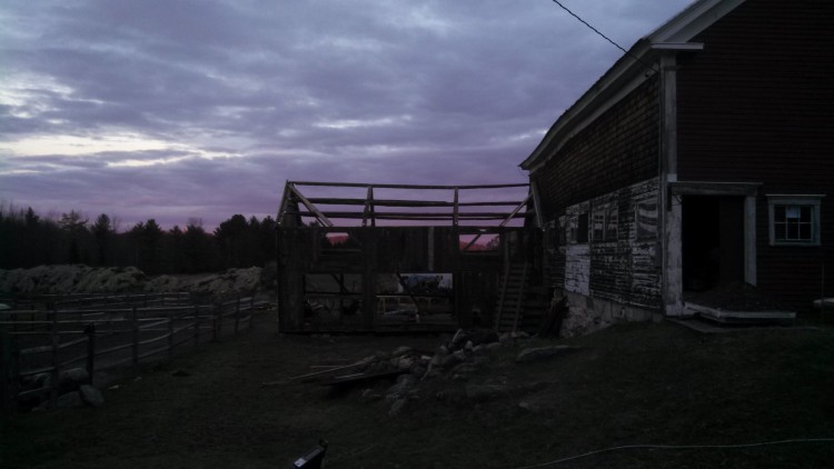
Brock standing
Brock’s Barn was located at Brock’s Crossing in South Berwick, near Slut’s Corner (the etymology of “slut” is facinating!). Simeon Brock bought the farm in 1790 and lived there with his wife, Judith, and their five children until his death in 1814. None of the children married or moved from the property. The youngest, Deborah, began working for the Portsmouth Manufacturing Company when she was 23. She was known for walking the mile and a half commute to the textile mill and for her thrift. Deborah managed the farm until she died in 1883 at the age of 74.*
Two barns in one, 18′ x 18′ extension on the left, 28′ x 42′ on the right
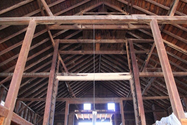
The Brock barn was actually two barns in one. A smaller, earlier 18′ x 18′ frame was expanded with a 28′ x 42′ frame. The rafters and ties of the former were extended to match the dimensions of the latter. Above, you can see the two adjacent posts where the gable ends of the frames meet. The 18′ x 18′ frame appears to have been built earlier, as the joinery was clearly retrofitted to expand the footprint and raise the peak to match the larger frame.
18 x 18 barn, original roof framing lower right. The ridge was raised, and roof plane extended.
Both frames have hewn timbers and scribed joints. Both frames exhibit the English tying joint, where the plate crosses over the post, parallel with the eave, and the tie beam crosses over the top of the plate. The interior face of the post, about half its thickness, extends past the plate to join to the tie beam with a teasel tenon. Both frames are eave entry, which was an earlier, “English”, floor plan. Both frames are early enough that it is difficult to date them definitively. The larger frame has up and down sawn braces, some of which exhibit the natural curvature of the limb, as above, but this does not date it. The first saw mill to operate on the neighboring falls was established in 1634. The 28′ x 42′ frame is also distinguished by much larger timbers, especially the lower tying girt and longer braces. Based on framing methods alone, it could have been constructed anywhere between 1790 – 1840.
English tying joint joins post top to plate and tie beam
Given the history of the property and surrounding town, we suspect that the 18′ x 18′ barn was built at the time Simeon bought the property in 1790. The smaller frame may have preceded the Brocks, but the only evidence is that they so drastically altered it. The 28′ x 42′ frame may have been built towards the end of Simeon’s life and appended to the smaller frame without any retrofit. The craftsmanship of the alterations to the 18′ x 18′ is significantly later and of lower quality than either barn frame. Some time after Simeon’s death, one of his children or one of Deborah’s farm hands may have extended the barn across the gable, and raised the ridge height. These are the histories we write as we repair the frame, fine-tuning each tenon and scarf joint.
Post scarfs on parade, photo by Dave Ewing
The Jennisons bought the 28′ x 42′ frame. Dave, Tom and Dan performed the frame repairs, and the results are stunning. Standing, the barn is defined by its array of post repairs. Each scarf joint was designed to maximize the preservation of original wood, and withstand the array of forces endured by each post. They planed the new timbers and fared their edges to blend seamlessly with the old.
Bent assembly, photo by Dave Ewing
Dave enjoyed the opportunity to work consistently on timber frame repairs. Nearly the entire roof system was in good shape, and he said, “getting to preserve that was a joy.” He also thinks that part of the reason the rebuilt barn looks so good is that all the new timber ended up in the same quadrant of the barn, in the new loft. The crew repaired the barn in our shop in Nottingham, NH and fit the bents together inside the shop. Then they disassembled the frame and transported it to its new home in Lee. Nearly the whole crew attended the raising, and both Seths and Brian assisted with the finish.
Jennison Barn, rebuilt. Photo by Josh McNally
Charlie Jennison plays saxophone and teaches music at Exeter Academy and UNH. He wants to the barn to serve as a concert space, and we hear that they’re already hosting successful events. Along with the outdoor sculpture gallery across the street, the Jennisons are creating an art enclave in Lee, and we’re proud that the barn gets to be a part of that.
The following photos of the finished Jennison Barn are by Josh McNally. Visit our Flickr page to see photos of the two frames before they were dismantled. Brock’s 18′ x 18′ frame is dismantled and looking for a good home.
The client’s wedding was in a week, and the barn in which he’d marry was in pieces on the ground. It was crane day, and a Friday, two things that don’t usually go together. In the worst case, a crane day on Friday means you don’t have an additional weekday in case you hit a bad snag; in the best case, it means the crane operator wants to get home, and the roof frame flies in fast and loose. In a week we’d complete a job started almost exactly four years earlier. Back then, Arron was patrolling the net, looking for a barn in need of saving, and spotted a damsel in West Poland, ME. That Saturday, he dragged his teen-aged son with him to visit the barn and get some driving practice. The frame was for sale, but not the land beneath it. It would need to be documented, disassembled, repaired and rebuilt elsewhere. When Arron arrived, another potential buyer was already poking around.
Before (September 2011)
Arron wanted to repair the barn, but needed a buyer; Charley wanted the barn, but needed someone to repair it. It was a good match. Since then, PTF has embarked upon a number of projects with Charley, most notably the disassembly, repair and rebuild of his Carpenter’s Shop two winters ago. The West Poland barn was neatly stacked in a Dairy barn at his home, awaiting its turn on a long to-do list. This fall, as Arron’s son prepared for his sophomore year in college, PTF erected a barn that had spent four years being designed and refined in Charley’s head.
Barn Frame Iso with transparent grade
Charley needs the barn to house his three draft horses, donkey and a flock of sheep. The draft horses wouldn’t fit under the barn’s original girts, 6′ 4″ above the sills, about 6 inches shorter than your standard doorway. He designed a foundation that raised the posts 2′ 8″ above grade, creating 9′ of clearance for the horses. The perimeter posts are each tenoned into a sill, which rests on a foundation wall. Each drive post lands directly on a 8″ x 8″ granite pier. Precisely 7′ tall, the piers rest directly on two longitudinal footers, 4′ below grade. A frost wall was poured between the posts; it’s top level with grade. Each post is point loaded upon a foundation wall that extends below the frost line and rests on a connected footer. This will prevent the posts from moving due to annual freeze and thaw. Ensuring that each drive post landed on its granite post required precise cutting, measuring and measuring again.
The barn we took down was built in the mid-19th century; it has hewn posts and both sawn and hewn girts. The center drive posts are more than 24′ tall, and are joined directly to the rafters. The ties are discontinuous, the outer tie mortises over the eave post, and tenons into the drive post. The plate is also discontinuous and is dropped eight inches below the top of the post. The original barn was almost square in plan, 38′ x 39′. With all that livestock, Charley needed larger bays, and decided to extend the length of each bay from 9′ to over 13′; the rebuilt barn is 38′ x 56′.
Tie Girt Scarf Fix
In early August, our first task was to repair the bents. Eighteen of twenty original posts could be reused or repaired, and thirteen of the original tie girts were salvageable, most requiring face fixes to their outer ends. All of the original braces were nailed, and we replaced them throughout with mortise-and-tenoned braces. Originally, the barn contained no loft girts within the bent beneath the ties; the loft joists had rested on top of eave and drive girts. We inserted loft girts into the bents, to better connect the eave and drive posts. Each drive post was 24′ long, hand-hewn, and twisty. We used the traditional scribe rule method to install the new framing members. Using a transit, we built a level “table” on which to assemble the bents. The “table” is eleven stacks of 6″ x 7″ cribbing laid out to support the post feet, the joint between tie girt and post, the joint between tie beam and post, and the rafter apex. We laid out each post and shimmed it level. Considering the twist of the posts, we leveled by measuring off the arris. On each timber, the two best faces are established as “reference” and the corner where they intersect is called the arris. The handhewn surface may vary, but this way, our posts will still line up on the foundation. We fit the tie beams and checked measurements, squaring the bent by measuring across diagonal corners. Then we laid the new loft girts and braces out on top of the bent and used a level and combination square to scribe their shoulders to the associated post or tie girt. Not one of the original rafters could be salvaged, except maybe for use as a dugout canoe. We increased the size of the rafters to 7″ x 9″ and used string lines to scribe them to the bents. Due to the time restraint, we weren’t able to scribe the actual rafter timbers to the bents until their final fitting before crane day, and this ultimately pushed our crane day from Thursday to Friday. Next time, we’ll go slower and scribe rafters while we’re fitting the rest of the bent.
Mortise in sill to accept twisted post
By the time the bents were fit, the foundation was poured, and sill timbers cut. We were able to use the foundation as our “table” while we fit the eaves. This was ideal, because the drive posts could be laid directly over their granite piers. After the posts were laid out and square, the new, longer eave girts and plates were laid out and scribed. This is where the use of reference faces becomes essential. During assembly, reference face is always up. When fitting the eave walls, the reference face is 90 degrees to the reference face that was used to fit the bents. By consistently measuring and laying out the timbers to the same point along the arris, we can ensure that the eave joinery will fit tightly when the building is standing.
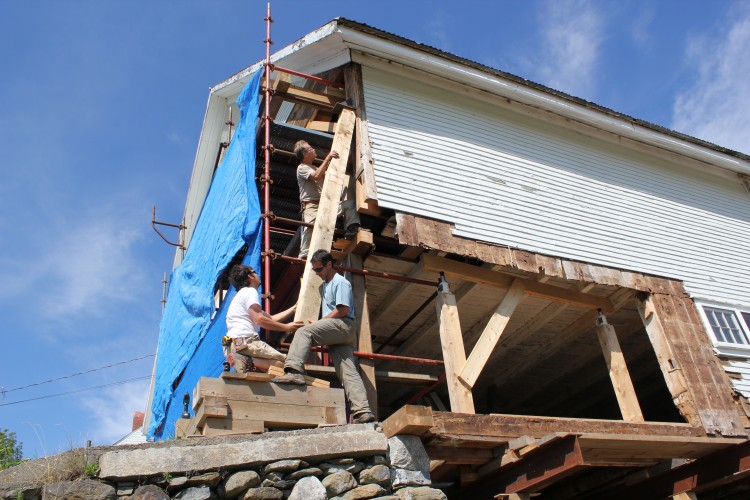
Fitting the Final Rafter
Crane Day required the entire crew. Placing the barn on a high foundation wall meant the loft girts were high, 9′ above grade, and the plates were 7′ above that. For each timber, there needed to be a crew member on the ground and two more up high. We used blue frame staging along each eave and a scissor lift in the drive. After bent one was raised, a dozen more timbers needed to be placed (loft girts, drive girts, interior post and braces) before bent two could be flown in and connected. When the bents were all standing, the 7″ x 9″ x 25′ rafters were each flown in and fitted over the drive posts. Lastly, the crane set the purlins. It was 3:00 pm on a Friday, and they came in fast.
Sheathing the Roof
Sheathing the roof that Monday was exhausting, the boards were hemlock, and green. But we finished with a couple days to spare. This barn has had a long life. Like marriage, it is the product of hard work, thoughtful attention, adaptation and love. We wish Charley and his bride the very best.
With spring in sight, it’s easy now to look back with pride at the frigid months spent repairing the frame of the Todd Farm Barn. Shawn Perry, Jesse Turgeon, Reese Crotteau and Brian Cox worked diligently to repair posts, tie beams and undercarriage of this large transitional frame in Rowley, MA. When all contractors have completed their repairs, the barn will expand space for Todd Farm antiques. Todd Farm flea market opens this Sunday, April 13th (experienced treasure hunters recommend getting there early, 6 am early). Below, Brian illustrates and describes PTF’s repairs, including photos of some sweet tie beam scarfs.
The Todd barn measures approximately 45’ x 65’. It dates from the early twentieth century and is a transitional frame, with little joinery. With the exception of the girts in the undercarriage, most frame elements are nailed. It has doubled top plates of nominal lumber, nailed together, studded eave walls, and as you would expect, studded gable walls above the tie beam. PTF was contracted to complete structural work, illustrated in the images below.
North eave looking west. Photo by Brian Cox
Lifting brackets were placed on each of the seven posts along the north eave, as the entire length of sill needed to be replaced due to extensive rot. Cribbing piles were placed under the center of the lifting brackets and jacks and jack posts were installed. The barn was lifted only a minimal amount in order to cut the nails holding the studs at the sill level.
North eave sill, one half of a bladed scarf joint. Photo by Brian Cox
The existing sills along the north eave were approximately 6”x 8”, with a 2” ledger on the inside face, which supported the joists. We repaired this sill using a bladed scarf joint, with the blade, or table, being 24”. The sill timber measures 8”x 9”. We chose to install an 8”x 9” based on the dimensions of sills in place in the remainder of the barn.
North eave scarf, where sill timber #2 meets sill timber #3. Photo by Brian Cox
There were a total of five sill timbers cut and installed along the north eave. A marriage mark made in pencil was used for easy identification purposes. Upon completion of the sills being cut, they were fit and drilled with a 1” ships auger bit. Hardwood pins were driven after stringing the face of the sills and a straight line on all five timbers was achieved. Mallet marks are visible, where gentle coaxing was needed to drive the timbers into position. Knots prove to be great driving locations, when available.
Cribbing piles in basement. Photo by Brian Cox
We built piles of 6”x 7” hemlock cribbing to support steel I-beams, which were used to hold the joists and girts off of the foundation while a new foundation wall was built. The new foundation was a poured concrete wall topped and finished with brick. Hydraulic jacks placed beneath the steel were used to level each bay while eave posts were lifted using jacks, brackets and dead men. A 2″x 6″ ledger was fastened across the posts, and timber-locked to each stud in between. This ensured that the studs were lifted along with the posts and girts. Where viable, we left sheathing and clapboards in place. This makes the wall a little more difficult to lift because the sheathing and clapboards hinder fine tuning.
East gable tie beam, from exterior. Photo by Brian Cox
On the east gable, we built wedgelock scaffolding to the tie beam level. Upon labeling and demo of sheathing and clapboards, we discovered what an old colleague of mine would refer to as “termites holding hands”, or in this case, ants holding hands. We found, as illustrated in this image, significant ant damage. Many braces and studs above the tie beam no longer reached the tie beam and, where they did, there was no structural surface remaining that could accept any compression forces. At this level of rot, the sheathing in this area was structural. This damaged material was removed and, where sound material was encountered, a 24” bladed scarf was cut and a new corresponding bladed fix was installed.
East gable tie beam fix, from inside. Photo by Jessica MilNeil
One end of the fix and original material shown in above image. The studs in this gable were cut away and compression blocks and sisters were added. Similarly dimensioned fixes and sisters were installed.
Bent #4 floor girt repair. Photo by Brian Cox
We uncovered additional rot in the floor girts in the barn. The girts running eave-to-eave were continuous and the drive girts were discontinuous. Temporary deadmen were used to stabilize the joists adjacent to the girt repair. The drive girt between bents #4 and #3 was replaced concurrently. Beneath the girt, we installed a permanent dead man, topped with two crossed oak bolsters. This configuration was placed beneath each drive post point load. A lead barrier was placed between the concrete footer and the post bottom at each of these locations.
Bent #5 tie beam fix. Photo by Jessica MilNeil
Water infiltration at the cupola lead to deterioration of the tie beam at bent #5. A tie beam fix, with a bladed scarf on each end, replaced the center segment of the existing tie. A 6” x 7″ bolster was then placed under the tie beam fix. This bolster is also in place at bent #4. There was a loft above this area that was removed prior to work commencing. Note the lack of bracing from drive post to tie. There are braces from the eave posts to the tie, and these are nailed in place, rather than connected by mortise and tenon. The rafters are full length from peak to eave.
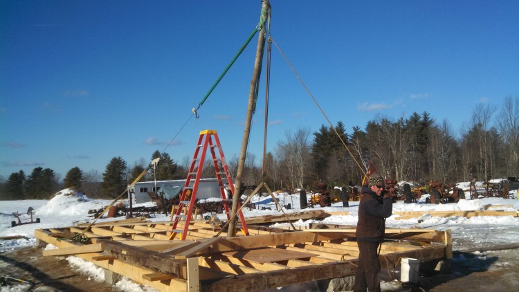
Here’s one to please our 11-year-old selves, and the folks over at Low-Tech Magazine: we raised the Carpenter’s Shop using a gin pole. This is a simple and traditional method for raising a timber frame by hand, and straightforward solution to a site with little crane access. It’s constructed from a long, straight pole with a block and tackle hanging from the top, and two guy lines (in our case, come-alongs) that help to counter the weight of the pole and the timbers, and locate the posts in their mortises.
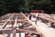
This is an eave assembled on the deck. A bent assembly isn’t pictured, but looks similar, rotated 90 degrees
After test-fitting the eaves, we assembled the first bent (like a bread slice of the timber frame, parallel with the gable) flat on the deck so that the post tenons were hanging over their corresponding mortises – so that, when rotated to vertical, the tenons would “tip” into their holes. The pieces of the bent were fit together so that the tie beam was placed towards the center of the deck and all the exterior reference faces were facing up. The bent was fit, measured, bound, remeasured, and then pinned and wedged. Each bent has two ascending and two descending braces, creating an especially stable and sturdy frame. What original wedges couldn’t be reused were cut from seasoned white oak. It was satisfying to knock the wedges in tight, locking the half dovetail tenon at the end of the tie beam to the sloped shoulder of the post’s complimentary mortise. Ah, wedged half dovetails. We screwed stop blocks to the corners of the sill so that the post feet couldn’t slip off the deck as the bent was raised. We also screwed two 2x8x16′ pieces of KD to the exterior face of posts, at the top of the post, so that they could be used as kickstands once the bent was nearly vertical. That completed the first bent assembly.
Lee cut a maple sapling that was at least 18′ long, which is half again as tall as our posts (we realized through trial and error that this could have even been a little longer, but you could realize that sooner using a physics textbook). He attached a block and tackle to the top end of the sapling (again, if one was so inclined, we could calculate the exact number of pulleys needed to create the mechanical advantage to pull the bent up using human-power, but we had a tractor, so we used the block and tackle that Lee had). Directly beneath the block and tackle connection, we attached two 24′ come-alongs. That completed the gin pole assembly.
Gin Pole in Tension
We screwed a U-shaped block to the deck at the foot of the gin pole, near the center of the frame, to keep the foot from slipping out of place. The opposite ends of the come-longs were secured to the rear corners of the deck, so that the gin pole come-alongs and block and tackle created a peace sign on the deck (a peace sign without a circle, and with two extra long come-along legs). Scott and I lifted the gin-pole into a nearly vertical position, while Lee loped back and forth, tightening the come-alongs as we raised the pole. Working the come-alongs allowed Lee to center the top of the pole precisely over the bent. When the pole was leaning forward so that the block and tackle hung directly over the center of the tie beam, Scott pulled down tight on the block and tackle, connected the hook at its base to the center of the tie beam, and pulled down on the free end of the rope (pictured above). This created a stable triangle of opposing forces (block and tackle, come-along and come-along), securing the gin pole in place about 10 degrees from vertical. This completed the raising of the gin pole.
Scott pulled down on the raising rope, and, nothing happened. If we had not had the tractor at our disposal, we would have needed a block and tackle with more pulleys, and a rope with less stretch. As it was, we hooked that sucker up to a tractor, corrupting the purity of a hand-raising. For shame! Anyways. We attached the rope to the front of the tractor as high and as close to the top of the gin pole as feasible. I reversed the tractor and lowered the arm with all the grace of Kevin Bacon in Footloose as Scott monitored the post feet and Lee let out the cable on the come-alongs, incrementally.
First Bent, raised
Once the bent was lifted past 45 degrees, I set the brake, re-tied my shoelaces, and Scott and I used the 16′ pieces of KD attached to the tops of the posts to lift the bent to vertical, and seat the tenons in their mortises. We screwed the KD kickstands into the eave sills, and stopped to admire our work. With the kickstands in place, we were able to plumb the bent precisely. When we satisfied with the bent’s location, we moved the gin pole, and prepared to raise the second bent.
Lee in Tee at 10 degrees
The gin pole was not the only low tech technology employed at the Carpenter’s shop. Lee used an adze to cut the tenons of the first floor joists, allowing him to work in a tee shirt in single digit temperatures. After the bents were raised, we used a water level to level them. On sunny sites, it’s sometimes easier to use a water level than a laser. If you want to know more about either of these methods, please let me know.
New blue water level hung at reference corner
Sometimes the oldest technologies provide the best solution for the job at hand. From wedges and ramps to pulleys, I am surprised at how right my physics teachers were about the ubiquity of simple machines. When applied purposefully, with careful consideration, these approaches can be safer, simpler and cheaper. While I appreciate the romance associated with historic contraptions, ultimately, romance is not the reason we employ them. These technologies are selected when they are the most functional option for the job at hand. We were just lucky to have some fun with them up in Poland.
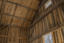
True-Randall Farm Barn, roof system from rear loft
Tie Beams are the defining component of a timber frame. They tie a barn together better than The Dude’s rug ever could. A tie beam crosses the gable at or below the plate (eave) level, and prevents the eave walls from spreading under the outward pressure of the rafters. Tie beams, more than any other element, identify the style of timber frame, be it English-tie, drop-tie, or interrupted. While a tie beam alone can’t date a building, these designs are associated with particular time periods; the English tie with the 18th and early-19th century, and the drop-tie with the 19th century (in Maine). I’ve written elsewhere about these impressive framing members, and the relative pros and cons to their design (Historic American Timber Joinery, by Jack Sobon, and made available by the Timber Framers Guild, is a fascinating and exhaustive source of joinery information). Below, I’m going to describe what goes into repairing one, in a standing building.
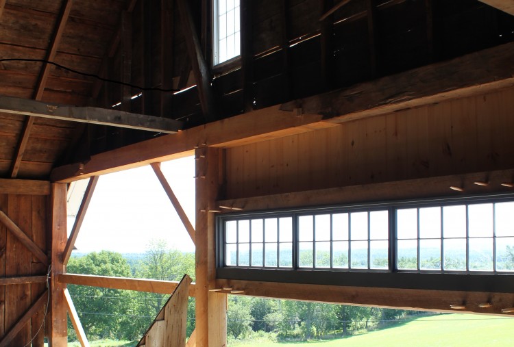
The owners of True-Randall Farm have a strong preservation ethic, combined with a desire to have their property serve their contemporary needs. They walked a fine line throughout the project, preserving every original, functional framing member, while installing a clean, contemporary kitchen in a long re-muddled connecting ell (preserving any remaining original framing even here, even though invisible). The house and barn on either side retain their original design and artifacts, as well as transitioning beautifully into a functional modern kitchen. The barn is visible through a sliding glass wall in the kitchen, where the expansive timber frame and associated repairs can be admired during meals.
Scott and Lee, laying out fixes
The repairs to the barn were extensive. We replaced sills, foundation and drainage, and shored up the undercarriage. Two posts were replaced, along with their adjacent loft girts. Unfortunately, pernicious rot in the tie beam was invisible until exterior sheathing was removed to replace one of the drive posts. One of the advantages to timber frames is that a beam can rot extensively before losing functionality, or before the damage becomes visible. This is also one of the disadvantages.
The True-Randall barn has endured a history of alteration and adaptive reuse long before PTF or the current owners arrived. According to the history researched and written by owners George and Karin Look:
In 1889 the barn was moved to its current position and connected to the house by an ell. Local history indicates that it was rolled across the road using oxen and logs and that a small American Elm run over during the move stood back up and grew into a giant tree in front of the barn. The roof was removed before the move and roof elements, including the purlins, were used in building the deck for the barn, which was converted into a bank barn. At the time of the move an original eave wall was moved to the east 6 feet to increase the size of the milking parlor to accommodate the new, larger breeds of dairy cows that were becoming popular at the time. Also, the new roof was built with higher pitch to allow for storage of more hay. The barn was in use in a dairy operation until the 1970s.
Series of c.1899 stop-splayed, undersquinted and wedged tie beam extension scarf
In order to extend the barn 6′ east, a scarf joint was cut into the east end of each of the tie beams. As its name suggests, a tie beam functions in tension and any scarf along its length must equally resist those forces as any link in a chain. PTF’s commonly used halved-and-bladed scarf joint (p. 47, Sobon) is a great joint, but wouldn’t necessarily be effective here. The barn-wrights in 1889 used a stop-splayed, undersquinted and wedged scarf joint (p. 49, Sobon) to extend the tie beams by six feet and accommodate a new milking parlor. The two inch wedges in this scarf push the two halves of the joint together, countering the outward thrust of the rafters. This wedged key resists that force better than the shear strength of one inch pins (as would be used in other scarves). Additionally, the wedges can be driven into the key with seasonal and yearly wood shrinkage. This adaptive quality of wedges is employed elsewhere in timber-framing, such as the wedged-half-dovetail joint used at the ends of the Carpenter shop’s drop-ties, and in the wedged-half dovetail at the bottom of the king post in the Abyssinian Meetinghouse. The beauty of the wedge in a king post truss is that, being oriented vertically, the wedge drops deeper into the joint as the wood shrinks, automatically tightening the joint, like a glacially-paced Rube Goldberg contraption.
Lee, Chuck and Scott strategizing on staging
The front gable tie beam was badly rotten due to water infiltration. Located at the top of Randall’s hill, the front of this barn endures an inordinate amount of wind-driven rain, indicating the window directly above as the most likely culprit. The 18′ section of punky, rotten wood extended from the center of the drive to within 8′ of the rafter-tie-plate connection. We were fortunate that the rot didn’t extend to the English tying joint at the eave, as the repair would have required more complicated rigging and joint-cutting.
One scarf half, on the existing tie beam
As it was, we built 3 levels of structural, wedge-lock staging across the plane of the front gable, extending from 7′ of lawn adjacent the gable into 7′ of the first bay of the barn. By crossing the upper ledgers of the staging with heavy, 8×8 rigging timbers, we were able to pick up the tie at two points, directly outside of the rot. The studs above were stabilized with a 2×10 hemlock ledger screwed across their faces. After the rigging securely supported the tie beam and framing above it, we carefully began to excise the rot. When we reached sound wood, we laid out half of a stop-splayed, under-squinted and wedged scarf on each of the two remaining ends of the tie beam. On the ground, we cut the analogous scarf halves on a piece of 9″ x 9″ x 18′ Eastern White Pine (we are currently avoiding the use of hemlock due to the preponderance of white mold).
Tie fix rising
We used a 1-ton chainfall, mallets and muscle to lift the repair into place and engage both scarves. The two hydraulic jacks allowed us to adjust the height either end of the existing tie beam separately, allowing us to dial into each scarf connection relatively independently. When each scarf was snugly fit, opposing wedges were driven in from each side, driving the halves of the scarf together and locking the repair in place.
Stop-splayed undersquinted wedged scarf repair, c. 2013
Repairs of this level require extensive stripping of sheathing and clapboards. In the case of this barn, the clapboards badly needed replacement anyways. Some had been replaced ten or so years prior, with low-quality claps; others had been “repaired” with a spray of drywall screws. Inevitably, the replacement of sheathing, clapboards and trim takes as much, if not more, time than the timber frame repair itself.
Completed tie beam repair
While the condition of this tie beam was an unfortunate surprise, we were happy to be able to amend the damage with a traditional repair that blended seamlessly with the history of the barn, and its previous alterations. I can only hope that next month, the full replacement of a tie beam in a two-story Greek Revival in Brunswick goes as smoothly.
I think most people on the crew have come across a frame that made them stop, and think, “Man, that’s the frame I’d build for myself.” I think I’ve found mine. It’s one of what will be three barns on a piece of property in Poland, ME – a horse barn, dairy barn and carpenter’s shop. We dismantled the horse barn over a year ago, on another property in West Poland; we’ll rebuild it next, and it’ll become a home for the client’s draft horses. The dairy barn is stabilized currently, and will need a complete undercarriage repair at a later phase. The dairy has some of the finest trim details I’ve seen on a barn yet, but it’s the carpenter’s shop that I love. It is a re-used frame, 17 x 30, with a drop tie, and purlin roof.
Dairy Barn, ain’t she precious?
To a lot of folks, the English tying joint is the pinnacle of tying joints, but the drop tie in this shop is pretty charming to me. In any barn, the tie beam is the timber located at or near the top of the posts, parallel to the gable; it prevents the eave walls from spreading under outward thrust of the rafters. In an English tie, the tie beam crosses over the tops of the eave plate and posts; it is connected to the plate by a half dovetail joint (on the flat), and to the top of the post by a teasel tenon.
Corner post removed, Scott leaning on loft girt, end of tie beam exposed
A drop tie beam is an early 19th century development, in which the tie beam is dropped below the plate by 2-5 feet and joined to the posts, directly. A collar tie is necessary to help prevent rafter spread, and the height of that collar tie is integral to it’s function.
Exterior of post, showing wide end of half dovetail and end of wedge on top
In this shop, the drop tie is connected to the posts with a wedged half dovetail. An extended mortise is cut into the post, with a sloped bottom. The tenon on the tie beam is cut with a half dovetail (on edge), which drops over the sloped face at the bottom of the post mortise. After the tie beam is inserted into the post, a wedge is driven through the top of the mortise, above the tie beam, to help lock the joinery into place. A major difference between these two tying joints is how it affects the raising of the barn; an English tie would require an eave raising, and a drop tie requires a bent raising.
Scott safely stripping
The benefit of a drop tie is that is provides higher head room in the attic story. In this shop, I thought the proportion of the room created at the attic level will be perfect for the client’s bench tools and hand work. The first floor will be used for machine work – the client plans to use the shop to restore antique sleighs. Both floors have enough headroom to spin things around and enough length to rip something as long as you’d like. It’s small enough to heat easily, and I especially like the way the light comes through the windows at the floor of the loft level.
Scott a-prying
Anyways, the carpenter’s shop was attached to the dairy, and was propping up its rear end. We dismantled the shop fully, both to repair it, and to move it away from the Dairy barn, which worked better for the site, and allows one to appreciate the beauty of the dairy more fully. It was a big help to have the client’s tractors on site.
Cutting in the snow is much better than cutting in the rain
Scott and Lee cut the replacement sill and post timbers quickly, and in the snow, too. They left for me the tie beams with the half dovetails that I love so. Lee followed his post work by cutting eighteen oak braces. The down braces at the loft level are part of what makes this drop-tie frame so durable.
Check out those down braces
Oak replacement braces
Last week, we used our 8th grade geometry skills to lay out the frost posts. With the help of an enormous excavator, and a little mason’s line, it was a breeze to lay out the posts to the dimension of the shop’s footprint, but we needed to use the Pythagorean theorem to figure out what our diagonals should be, and make sure that the frost posts were laid at right corners to one another. It is a great joy of my job to get to use the theorems I learned in geometry class.
Scott, plunges cog mortises into a floor girt with the chain- mortiser
Next week, we’ll be topping the frost piers with granite capstones, and laying and fitting the sills over the granite. Lee has his adze sharpened, and we’ll be using it to cut the first floor joists. We’ll cut the joists to length and drop them upside-down into their associated cog-mortises in the tops of the sills and floor girts. Sitting in the cog upside-down, the rough floor joist will be 4-5 inches proud of the surface of the floor girts. We’ll then use an adze to cut an angled shoulder in line with the inside edge of the floor girt and to cut a tenon on the end of the joist that is perfectly level with the top of the sills. After the tenon is smooth, we’ll turn the joists over, and they’ll create a perfectly leveled floor.
Scott and Lee surveying the site, that’s the barn frame stacked in the piles in the foreground
We hope to raise the Carpenter’s shop frame in time for Christmas, and then our client can start sheathing it over the Holidays. I hope he thinks it’s an awesome present, because I would.
Nov. 15, 2013 – When I tell people what I do, I sometimes run into the misconception that preservationists are single-minded, inflexible, and uninterested in innovation and design. It’s true that at Preservation Timber Framing we think that if a frame stands strong for 200 years, it probably has good design to thank, and that time-tested building details last longer. We also think it’s possible to combine contemporary design with the stewardship of a historic property, and achieve successful results. True-Randall Farm was just such an example. The connected farmstead required repairs to house, barn and ell. The clients have a strong preservation ethic and want to preserve the original framing members but they also wanted a functional kitchen with clean, modern lines. The ell had been extensively renovated by previous owners, and the clients decided to dedicate that portion of the house to the new kitchen. They preserved any original framing within the ell (and without) that remained.
Even working within a strict preservation ethos requires adaptability. The house and barn at Randall’s Hill retained most of their original elements and were repaired traditionally, with in-kind materials. Both house and barn had rotten corner posts, but the repairs to each post were entirely different in scope and in design.
Barn corner post removed, from interior
The barn repair was a more typical, and traditional, fix. It was also more extensive, because the rot extended above the girt that supports the right loft bay, and the frame was more accessible to repair. In order to get access to the post, we stripped the corner of trim, clapboards and sheathing. We affixed an L-shaped bracket, custom-made for lifting, to the exterior of the post, and built a cribbing pile beneath and just to the outside of it. Beneath the bracket and on top of the cribbing pile, we inserted a dead man (temporary post) and hydraulic jack, which would be used to level the corner, and support the weight of the post and roof above it (See first photo, above). We also inserted a deadman beneath the loft girts to pick up the weight of the loft (See “Barn corner post removed…,” center of photo).
Corner post, with center mortise repair
Lee carefully cut away the post where it was rotted, and removed the braces. With a circular saw, auger bit and timber framing chisel, he cut the female half of a center tenon scarf joint onto the part of the post that remained. We used a center-tenon scarf on this post to preserve both the reference (outside) face of the post and the inside face that was most visible. The fix was also oriented to resist any outward thrust that was transferred from the rafters.
Lee and his corner fixes, (the center tenon post repair is on the bottom, a repaired nailer is on the top)
Lee cut the second half of the post out of a large 10 x 10 timber, the same dimension and species of the piece that was removed. In order to fit the post fix into place, we used a free tenon at the bottom of the post fix (see diagram, below).
Installation of a free tenon
Lee cut an extended mortise into the front gable sill and a long open slot on the adjacent face of the post fix. After the post fix was installed, and the center tenon scarf was fit and pinned, a free tenon was inserted vertically into the extended mortise in the sill and slid into the slot in the post. The remaining mortise space in the sill was plugged with a wedge, and the free tenon was pinned into the post.
Barn front gable, rebuilt in place
After the post was fixed, I replaced the loft girt in the front gable, and neighboring braces, door post, and nailer. Unfortunately, this barn typified the worst case scenario involving hidden rot. Working in preservation we face a harsh reality in which, sometimes, significant rot can be completely hidden, and once rot is uncovered, it can’t be re-sheathed until repaired.
Open house
We also performed a post repair on the Federal-style house and, in contrast with the barn, we could disturb none of the interior surfaces. In this way, the repair was similar to the timber frame repair at the Marrett House in Standish, where the framing had become detached from the plaster and lath, but the plaster and lath still needed to be preserved, with early 19th century wallpaper left intact.
House corner post repair, installed.
The post requiring repair was located at the front-right corner of the house. We first noticed that the front eave and right gable sills were punky. The rot in this post did not extend upwards past the second floor girts, or inward throughout the post thickness, except at the very bottom. This fortuitous turn of events allowed us to repair the post with a three-stepped lap joint – cutting away the exterior surface of the post to the depth of the rot, and using epoxy and fasteners to install a new-in-kind repair that fills the negative space left by the rot. Relative to the post repair in the barn, this was a non-traditional fix, utilizing modern epoxy and fastener technology. It was the appropriate fix for the level of rot and its context.
House corner, post repair.
The contrast between these two methods of post foot repair, and the combination of traditional repair and contemporary use in the ell, shows that the best preservation is adaptable. Our process is developed from traditional methods, but it isn’t staid or prescriptive. Part of the reason we document the multitude of barns we come across is that they provide us with a greater variety of long-lasting approaches to repair. We’re always eager to learn a design solution that is new to us, it’s just that the best solutions we’ve found have been proven over 200 years.
Reading Dave Ewing’s paper on the history of moving buildings, I started thinking about the part lifting buildings plays in our work (it’s a starring role), and the part that screws and other simple machines play in that lifting (co-starring the skid steer).
Skid Steer as Narwhal
This year, we repaired a barn on Randall’s Hill in Montville. It was a big lift, and hold. The crew spent late fall and winter under the barn digging footers and preparing the ground for both the lift and the posts that would be installed below the undercarriage. The crew cut 6″ x 7″ cribbing into 4′ lengths and piled them, Lincoln-Log style, into ten boxes. Building cribbing piles is something of an art; the piles need to be perfectly level, and when they are neatly cut, they can be checked for plumb at the corners as they are stacked. We build with the 7″ on edge so that each layer is 7″ high. This allows us to slide other cribbing, laid flat on the 6″, in and out of the stack when it comes to lifting and lowering the steel with hydraulic jacks.
Dead men and cribbing piles, under the barn
We built a wooden track atop the cribbing piles, and placed rollers along them. Derek Davis, of Davis Dirtworks, inserted 35′, 1000 lb H-Beams under the building, and onto the rollers. The rollers we use come from our clapboard supplier, Steve Jeffery, from the center of the log that is left over from manufacturing radial-sawn clapboards. In the 1890s, they also used wooden rollers to move the barn, but instead of a skid steer, they used steer.
So, we slowly rolled the H-Beams into place, and then Derek threaded four 25′ I-Beams under the building (called the “needles.”) The entire grid was leveled across the cribbing piles and then raised to the underside of the first floor framing. We lifted sequentially, using hydraulic jacks set onto cribbing that crossed the “ladder rungs” of the cribbing piles. Considering that the throw of the jack was less than 7 inches, I was surprised that we finished lifting the grid the same afternoon that the beams were installed.
Barn, block, steel, steer
The beams were used to stabilize the building while the cinder block foundation was demolished and replaced with proper footers, frost wall, and timber posts that were tenoned to the sills above. Drainage was installed around the exterior to manage the water that formerly ran through the basement and contributed to undercarriage decay.
Demo day
Holding the barn with steel, cribbing piles, and dead men
One of our main tasks was leveling the posts. Over time, the sills and summer beams had sagged and spread to such a degree that the posts were all over the place. We determined a reference post at the beginning of the project, in the front corner adjacent to the connector ell. At each of the other 23 posts, we used both a water level and laser level to determine how far from level the top of each post was from the top of the reference post. One of the drive posts was more than 5 inches out of level; most of the rest ranged between 2 and 4 inches.
frost wall
New posted wall
When we were finished repairing the foundation, the steel beams were removed as they’d been inserted. It took an afternoon to lower the beams, using hydraulic jacks, cribbing pile rung by cribbing pile rung, and removed just as gracefully by Derek in the skid steer.
Elsewhere on the project, both during and after the insertion of steel, we repaired posts using a more typical method of lifting and holding, with brackets, screw jacks and jack posts. I will describe multiple approaches to post repair in an upcoming blog post, and more about Randall’s Hill over a series to be published this month. The barn was part of a much larger project to repair the house and barn, and renovate the connecting ell with a clean, modern kitchen. The completion of a project that combined honest, best-practice preservation and the installation of a high-modern contemporary kitchen required a clear vision from the clients and a lot of stamina. I look forward to describing our process in future posts.
If forced to choose, I think most of the PTF crew would choose hand-tools over machines, our chisels and mallet. Fortunately, we don’t have to choose, and one of the pleasures of our job is that we have a broad range of woodworking tools with which to solve the problems we face in the shop and in the field. There are those of us who drool over the machines, and those of us who jealously guard our antique molding planes. I tend to fall into the latter category, but I am here to admit that the three-year-olds were right. On a beautiful spring day, big yellow lulls and tall blue manlifts are even better than my little buddy Quinn thinks they are.
Barn and lull
A couple months ago, Shawn and I were facing the end of an enormous barn that looked as if it had been attacked by a pair of xylophagus tyrannosaurs. The two corners posts, and the sheathing around them, were absent, and the large triangle of the gable end teetered on a center post, which was significantly supported by a neighboring tree. The ends of the tie beam had rotted off just enough to disconnect from the eave plates, but not so much that their weight was reduced.
Interior frame
The framing of the barn is unique. A center drive post extends to the ridge, and is connected to the left eave by a tie beam. On the right, a strut rises to the right rafter, and the right rafter heel joins directly with the top of the right post. This gives the barn an incredibly high drive on the right side. The client wanted to repair the entire barn, but due to financial concerns, and the fact that the gable end was disintegrating before our eyes, we decided to sacrifice the last gable bent. If the condition of the last bent is cautionary tale about the consequences of roof leaks, the condition of the rest of the bents is a testament to good timber framing. Above the deck, the frame is in remarkably good condition; below the deck is frankly a little scary, and we will be stabilizing there next.
Gable triangle, afloat
The challenge was to disengage the gable end from the roof, without allowing it to crash into the barn, and to do that, we used the lull, man lift and chain saw to great effect. A man lift allowed us to stay above the fray, and carry the purlins and roof sheathing to the pile on the ground. Once the plate, purlins and roofing in the last bay were removed, the gable end was composed of a center post, braces, a tie beam and two rafters. The rafter-tie beam connection was completed rotted through. The stability of this limited framing in a stiff breeze is a testament to braced joinery. We were able to cut the rafters into pieces above the floating gable end tie beam, and then chop the center gable post into pieces from the top down.
Scribe line, 2 ft below the plate; the details afforded by man lift access
This job challenged my perceptions of preservation and the kinds of work I enjoy. This barn will serve as a good example of a preservation through triage and we were able to save an interesting structure for a client who had limited funds. I learned that big machines can be as attuned to their task as a hand plane, and just as fun on a sunny day.


")