Tag: Documentation

  • The Salvage Detectives, part 2

    The Salvage Detectives, part 2

    Unloading the trailer together
    Unloading the trailer together

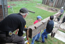
    An enduring feature of timber frames is that they can be dismantled and re-used. A traditional barn-raising, in which a community comes together to erect a frame in one day is preceded by weeks of joiners’ labor: cutting and fitting the posts, girts and braces, plates and tie beams. With the help of many hands, or a gin pole, or a crane, a frame can be raised or dismantled in a day. The relative ease of assembly, and more importantly, disassembly, is why we sometimes find 300 year old frames in 200 year old buildings. The act of preservation and adaptive re-use is a centuries-old tradition, regardless of the age of the frame itself.

    This year, engaging in this tradition has been equal parts fun and maddening. We were hired to decipher two frames tagged and disassembled by other contractors. One was the Reverend Morrison House, c. 1726, which was considered to be the oldest house in Londonderry, NH, and is being restored by the Londonderry Historical Society. The other is the French House, c. 1804, a 2-story hip-roofed house that was slated for demolition in Kingston, NH. It’s being restored by Charley and Sheila Foley, who are becoming old hands at this. Both frames were tagged before dismantling, but neither is attended by a full set of tagging drawings. We use tagging drawings like the picture on the box of a jigsaw puzzle. While we try to follow consistent tagging patterns, tagging a frame is pretty idiosyncratic. It’s unlikely that any two PTF frames would have tagging consistent enough to decipher the tags without drawings. That’s what made deciphering these frames such a…fun-show.

    SST7 and its old friend, Tom
    SST7 and its old friend, Tom

    The Rev. Morrison House was dismantled with tags similar to our own. Alphanumeric codes identified the location of the piece, the type of framing member, and its number in a sequence. We could tell, based on timber size, and the half dovetail at its end, that SST1-SST7 were tie beams. But was SST1 at the outside wall of the west ell, at the west gable, or at the east gable? And what did SS mean? That one remains a mystery.

    South eave, prior to dismantling. Photo courtesy Londonderry Historical Society
    South eave, prior to dismantling. Photo courtesy Londonderry Historical Society

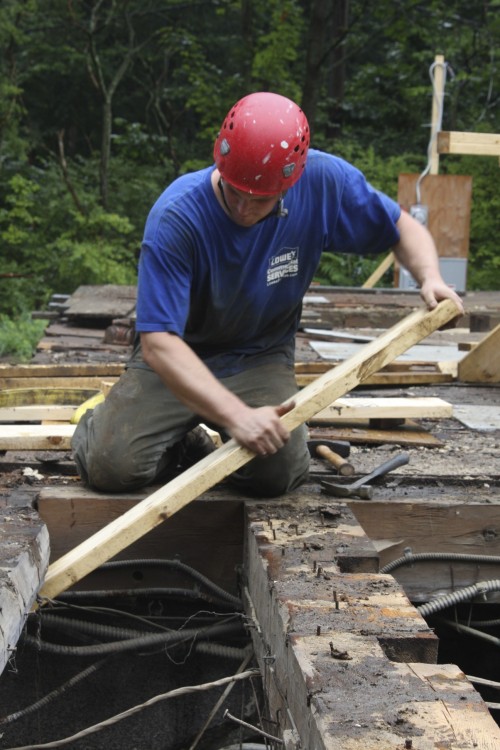
    Although a disassembled frame looks a little like a giant’s game of pickup sticks, it’s actually pretty easy to decipher how each timber was used. The joinery at either end of a timber communicates whether it was vertical or horizontal, and the joinery along its length tells us a lot about it’s location.

    Knowing the English tying joint allows us to identify the timbers that establish the overall dimensions of the building. This joint is where the post, plate, tie beam and rafter intersect. The plate is a timber that runs parallel to the eave at the cornice and passes over the exterior half of the eave wall posts. The tie beam crosses the plate, directly over a post and directly beneath a principal rafter. Tie beams prevent the eave walls from spreading under the outward thrust of the rafters. The end of the tie beam is cut into a half dovetail, and performs a mechanical task that contemporary builders assign to metal fasteners. More about tying here, and here. The plate accepts the tie in a half-dovetail-shaped mortise. In order to secure all this framing, the post is joined to both plate and tie. It is flared at the top, sometimes in an iconic, stepped “Gunstock” shape. The interior half of the post extends vertically past the plate and terminates in a “teasel” tenon, which inserts into a mortise in the tie beam.

    Tie beam end with half-dovetail and rafter mortise
    Tie beam end with half-dovetail and rafter mortise

    We could identify tie beams by the half dovetails at either end, their size, 11″ x 11″ x 20′, and the long rafter mortise located right over the dovetail. The joinery in between will tell us whether the tie beam was located on either end of the building or across the middle. Tie Beams are located above the posts at the level of the attic floor. A tie beam from the gable end will have open cog mortises to receive attic joists along its top and interior faces. It will have closed stud mortises along its top and bottom faces towards its exterior, reference face. The reference face will most likely have a series of fastener holes left over from the sheathing. A tie beam from the middle of the building will look different. It will have cogs for attic joists along both sides. It will not have stud mortises on its top face, and it may or may not have stud mortises along the bottom, for partition walls. It was easy to tell the EPlate1 and WPlate1 were gable tie beams and the TS1 and TS2 were the interior ties. The carpenter who dismantled the building apparently considers all major beams that ring the post tops “plates” and, you know, that’s his prerogative. I guess he didn’t read this.

    Tie beam end in plate pocket
    Tie beam end in plate pocket

    Plates, as we define them, run along the eave across the tops of the posts. In older timber frames like the Rev. Morrison house, they are smaller than tie beams in section, 6″ x 11″, but longer: 30′. The Reverend Morrison House has a long shed off its north wall and a shed off its west wall, too. The north shed plate was much smaller, 5 1/2″ x 9″, but 46′ long. This little plate received the short ties SST1-SST6 in an evenly spaced series of dovetail mortises. A plate will have post mortises and stud mortises along its bottom face. In18th and early 19th century timber frames, “English” timber frames, the plates will be the longest continuous framing members.

    Gunstock post tops. Plate tenon on top, teasel below
    Gunstock post tops. Plate tenon on top, teasel below

    In an “English” frame, the post will be the easiest timber to identify. The Morrison house had beautifully stepped gunstock posts, 14′ 3′ long, 7 1/2″ x 9″ at the bottom and 8″ x 12 1/2″ at the top. The plate and teasel shoulders are offset from one another by two to four inches and the end tenons are oriented 90 degrees to one another. A corner post will have brace and girt mortises along two outside faces. Interior eave posts will have brace and girt mortises on opposite faces, and in a two-story building like Morrison, a second floor girt mortise on its interior face. The orientation of the stub tenon on the bottom of the corner posts will indicate how the original perimeter sills were arranged.

    Perimeter girts will contain joist pockets that reveal joist orientation and joist layout. The Rev. Morrison house had an enormous chimney girt, 9″ x 14 1/2″ x 18′ 8 1/4″, and second story summer beam that connected the chimney girt and the east gable end girt, 10″ deep by 16″ across.

    Saltbox west gable. Image courtesy Londonderry Historical Society
    Saltbox west gable. Image courtesy Londonderry Historical Society

    Once the timbers were identified, we were able to arrange the second and attic floors on the foundation that had been poured before the untimely death of one of the project coordinators. Just when the pieces were starting to fit together, the real mystery of this house was revealed. At the time of its dismantling, the building was a traditional saltbox shape. There were three bays, 12′, 8′ and 20′ wide, measured from reference to reference, west to east.  We were told that the West bay (12′ wide) was a later addition, and the plates confirmed this.

    West end of plate, upside-down
    West end of plate, upside-down

    The ends of the plates were totally weird. They terminated in a sloped, stepped shoulder that we’d never before seen in so many years of investigating scarf joints. The end of the plate was long incline, that was sliced to half its width, as in a sloped, vertical lap joint. But the shape of the joinery wasn’t the weirdest thing about the plate. The weird thing was that it extended past the second bent, past the second pair of posts, by about sixteen inches. While the ends of some tie beams extend past the eave walls to create an overhang, that is a later style that was clearly not the case in this building. The overhang is not mirrored on the opposite gable end, and the ties do not overhang the eave walls. The building could not have originally ended at the current second bent, because there would have been two oddly shaped plate ends poking out of the west gable end of the building.

    West end of plate, with extension in place
    West end of plate, with extension in place

    But the length of the plates remained a curiosity, why did they extend west, past the outside faces of the posts? Additionally, the west gable wall posts were not continuous like the posts in the rest of the building. Ultimately, we determined that there were a pair of short teaseled posts on the first floor, with their teasels facing east, towards the main building. Originally, these posts were topped with a tie beam at the second story level, running perpendicular to the gable. Later, the tie beam became a second floor girt. A second pair of posts were cut and stacked atop the first, their teasels facing one another and linked with a tie beam parallel to those in the rest of the building. A single story ell preceded the saltbox roof on the west bay. Photos from the dismantling revealed that the chimney, located in the center, 8′ bay, was built with three fireplace openings, facing East, North and West. The fireplace opening and plate length indicate that a west-end, shed-roofed ell was original to the structure. The weird sloped shoulder cut into the end of the plate originally received shed rafters.

    West gable tie beams, original and added. Later gable end tie is up top
    Tie beams, early and late. Later tie beam “WPlate” is up top

    Investigating the tie beams confirmed our suspicions. When the building was dismantled, the tie beam on the west gable end was labelled “WPlate.” The next tie beam in was labelled TB1. TB1 served as the west gable tie beam when the building was built around 1726. Above, WPlate and TB2, a mid-span tie beam, lay next to one another. You can see attic joist pockets in TB2, and that they are laid out evenly until they get to the chimney mass, where there is a gap in the sequence. Both tie beams are hewn, but the hewing in the upper timber is more crude, and consistent with the quality of hewing on the plate extensions. The hewing in the rest of the frame was consistent with the fine hewing of the lower timber. The later timber is still quite early, and contains a number of wrought nails. This indicates that the west bay was converted from shed roof to salt box in the first quarter of the 19th century, at the latest.

    Morrison House Isos
    Morrison House Isos

    It took us nearly a week to extract the timbers from the trailers, decipher their use and document their dimensions. We used that information, along with dismantling photographs, to create a scale 3D model in SketchUp. Using this information, the Londonderry Historical Society can restore the building, and decide the time period to which they will interpret. Ultimately, deciphering a dismantled frame is like a Times crossword puzzle, the degree of difficulty is matched by the feeling of pride and satisfaction in the solution.

  • David Ewing to present at 2013 National Preservation Conference

    David Ewing to present at 2013 National Preservation Conference

    Dave, removing sheathing from the Demeritt-O'Kane House
    Dave, carefully removing sheathing from the Demeritt-O’Kane House

    PTF’s own David Ewing will present his paper, “Moving Historic Properties: A Valid Method of Preservation” at the National Trust for Preservation’s 2013 Conference in Indianapolis, IN.  Inspired by his experience dismantling the Demeritt-O’Kane house, the paper reviews the history of moving buildings and includes the example of a Boston apartment building which was moved at the rate of one inch per minute.  The move took three months, and the apartments were inhabited continuously.  He argues that the threat of demolition makes careful dis-assembly or intact movement a viable option for preservationists, as well as environmentalists.   From the abstract:

    The practice of Historic Preservation fundamentally involves the response to threatened historic places, buildings, or properties. Those involved in this professional field have the responsibility to use whatever means necessary to successfully thwart the deterioration or demolition of historic structures. For that reason preservationists must consider the merit of all potential methods. This paper investigates the evolution of building relocation as a method of protecting the resources found in the built environment. Furthermore, it explores the technological advances in the practice of relocation, the restrictive guidelines of National Registration Criteria and environmental implications in a thorough understanding of how relocation is a worthy option in the preservation of historic places.

    Dave will participate in a panel discussion on “Re-Booting Preservation for New Audiences.”   He is pursuing a Masters of Design Studies (MDS) in Historic Preservation at the Boston Architectural College, and his paper was selected competitively from a pool of preservationists from around the country.  Dave joined PTF after a summer internship through Maine Preservation, which PTF supports as a way to give preservation professionals headed for the office some time in the field.  We persuaded Dave to stay out in the field with us a little longer, and this paper is evidence that he’ll keep a boot in both environments.

    Dave, removing floor joists at the end of a long two days
    Dave, removing floor joists at the end of a long day
  • O’Kane Notebook XI: Demeritt Notebook?

    Weather-joined Sheathing
    Weather-joined Sheathing

    When I embarked upon a career in wood, I wondered whether I should become a furniture-maker, and construct finely joined objects of beauty, or build houses, which provide a lot more utility to people.  I soon found that it was a false dichotomy; working in preservation, I can work on buildings that are constructed like furniture.  On the building we’ve been referring to as “The O’Kane House,” I’ve written previously on the finely-proportioned trim, and the stoutly-joined frame.  Even the sheathing is weather-joined, creating a water-tight envelope, and the windowsills are grooved on the bottom to sit down tight over the sheathing.  The carpentry employed at O’Kane isn’t ostentatious, but every day I am inspired by the craftsmanship employed at each phase of its building.

    Given this gushing, we think that carpenter deserves some credit.  “The O’Kane House” is a bit of a misnomer.  For a long time, the building UNH now calls the O’Kane House was referred to as “The Demeritt House” in reference to the Demeritt family who built it, and lived on the land for more than 200 years.

    In July of 2001, Jim Garvin*, the New Hampshire state historian, wrote an Individual Inventory for the NH Division of Historical Resources for the Demeritt House, one of the steps for applying for its placement on the National Register of Historic Places.  In reading the report, I expected a bureaucratic list of dry historical attributes, but discovered instead a well-crafted narrative exploring the house’s former residents and their relationship to its architectural significance.  I encourage anyone who has been interested in the O’Kane House to read the whole report, here.

    The house was built for Israel Demeritt in 1808, on land that had been granted to his Great-grandfather, Eli Demeritt, before 1700.  Israel inherited the land from his father, Captain Samuel Demeritt, and replaced his father’s two story house with the one we so recently dismantled.  It was likely built by his brother Nathaniel Demeritt (1751-1827), a joiner who is known to have built a neighboring house with his son, the Rev. William Demeritt in 1819.

    If Nathaniel was indeed the builder, there were architectural consequences.  First of all, by 1808, Nathaniel would have been 57 years old, which explains why the house is so conservative in its layout and plan.  The center chimney and first floor layout resembles other houses that began to appear in coastal Maine and New Hampshire shortly after 1700 (pg. 98 A Building History of Northern New England).  

    Floor Plan, two-room deep house, by James Garvin
    Floor Plan, two-room deep house, from A Building History…, by James Garvin

    Conversely, the interior trim is far more contemporary and heavily influenced by Asher Benjamin.  The casings in the front entry are elaborate, and Garvin’s report cites Plate 1 of The Country Builder’s Assistant and Plate 11 of The American Builder’s Companion as possible influences.  I found a couple other possibilities in my copy of The American Builder’s Companion: in the top left corner of Plate 27 of  is an example of a cornice that is very similar to the crown in the second floor front hall, and Plate 35 illustrates an example of reeding similar to that found in the Blue Chamber.  I don’t own a copy of the Country Builder’s Assistant, but Nathaniel Demeritt did!  His name is written in a second edition housed at the New Hampshire Historical Society in Concord.  Concord readers (Hi, Mom and Dad!) go check it out.

    First Floor, Demeritt-O'Kane House
    First Floor, Demeritt-O'Kane House

    Nathaniel Demeritt’s age and life experience determined the design of his brother’s house.  His commitment to traditional techniques determined that the house was stoutly built, but his openness to Asher Benjamin’s new forms and proportions allowed him to trim it out in a style that was lasting.  People often ask me to define “preservation carpentry” and my stock answer cites our use of traditional joinery and appropriate techniques.  I mention that as Preservation Carpenters, we still get to work on houses (and barns, and steeples) that are built like furniture, which is something that can’t often be said of contemporary buildings.  But one of the best parts of preservation, and something that I have tried to express through the O’Kane Notebook posts, is the connection to builders like Nathaniel Demeritt.  He faced so many of the choices and challenges we still face today, and it is satisfying to uncover tangible examples of his decisions in the Demeritt House.  Demeritt relied upon proven tradition to help him design a sturdy, lasting frame, and watertight sheathing, but he also made room for innovation, and style, and took inspiration from the pages of Asher Benjamin’s books.  In rebuilding the Demeritt House, we will face a similar dilemma.  We have committed ourselves to using traditional techniques to repair and rebuild the remaining 85% of original material, but we face choices with regard to those couple of rooms that contained no original material, and will be needed for modern conveniences.  We can only hope that we will be as successful as Nathaniel Demeritt in building new rooms of lasting style.

    *Jim Garvin wrote A Building History of Northern New England, which I previously referenced here, here and here.  Meeting him was a real thrill for me.  He is as nice as he is a great writer, two things that don’t always go hand in hand.


  • O’Kane Notebook VI: The Nuts and Bolts of No Nuts and Bolts

    Wall 105.A, Outlined.
    Wall 105.A, Outlined. Photo by John Butler

    This is post about a persnickety process:

    After a piece of trim is removed from an O’Kane wall, it is taken over to a photograph of that wall and traced with a fine tip marker.  The dis-assembler then writes a description of the piece on the item list for that wall and assigns it an item number.  The room number, wall letter and item number are written on a piece of masking tape, which is affixed to the upper left, backhand corner of the piece.  The piece is carefully de-nailed, and then a final “acquisition” number is etched into a patch of white shellac using a Dremel tool.  The piece is wrapped in shrink wrap  with his cohorts, and tightly stacked in an assiduously organized, and mapped trailer.  I have just finished re-tracing all the photographs of those walls which have been completely denuded.  The results, below:

  • O’Kane Notebook IV: The Ghost Pantry

    Blue Parlor Wall, Dismantled
    Blue Parlor Wall, Dismantled. Photo by John Butler

    One of the first treasures we uncovered at O’Kane was a wall of horizontal featheredge sheathing painted in bright yellow.  It was hidden behind plaster in the Blue Parlor, and had shadow lines delineating where once there were shelves.  Where the boards terminate, on the left side, we think there was originally a wall, creating three rooms in the back half of the house.  Two smaller rooms flanked the Blue Parlor with its large central hearth.  The yellow paneling probably turned the corner, creating a pantry in what was originally the kitchen, given the large fireplace.  Throughout the house, we have continued to find boards and shards in the same chrome yellow, used as padding and strapping.  This helps to the date those walls, and solve the mystery of the house’s original layout.

    New Wall, Old Panelling


    Pictured above is the paneled wall that we uncovered in the room directly above the Blue Parlor.  The right portion of the paneled wall is original, and you can make out the hinges from the original door opening on the second panel from the right.  The door opening was filled with one wide, nondescript board and a board with the same chrome yellow paint and shadow lines.  During one period of renovation, this yellow pantry board was probably taken from the partition wall downstairs and installed upstairs to create what became a UNH student’s bedroom.

    We have found other pieces of this doorway elsewhere in that upstairs bedroom.  In the closet, the head casing was being used as a shelf cleat, allowing us to determine the width of the original door.  Time and again during the dismantling process, we are reminded to be thankful for that Yankee thrift.

  • Dismantling the O’Kane Farmhouse

    O'Kane Farmhouse, Full Frontal
    O'Kane Farmhouse, South Face, photo by John Butler

    Preservation Timber Framing has been involved in a number of museum projects in the past.  We reconstructed the Brown-Pearl and Manning Rooms for the Boston MFA, rebuilt the Moffatt-Ladd coachhouse in Portsmouth, and dismantled 16th c.  Carved Ceiling Beams for the Fogg Museum at Harvard, to name a few.  We are honored to have been a part of these prestigious projects, but where does this leave the many historic houses that remain on the chopping block?  There are a number of legitimate reasons that a historic building cannot be, and should not be, preserved on its original site and usually this results in the building being demolished.  Is it possible to take the standards used in a museum setting and apply them towards preservation in the private sector?

    O'Kane East Face, photo by John Butler
    O'Kane East Face, photo by John Butler

    The O’Kane farmhouse, c. 1790, typifies this dilemma.  It is currently located across from the Child Study and Development Center on the UNH campus in Durham, NH.  Thanks to the university’s stewardship, the farmhouse retains many original or early features, including indian shutters in many of the rooms, and very nearly its original room layout and partitions.  Much of the panelling is likely original, and the trim elements appear to have been hung during a Federal-era renovation.  But the Child Development Center needs to expand, and the Farmhouse is wildly inappropriate for that use.  Firstly, the original trim retains its original lead paint, and many decades of lead chips saturate the surrounding soil.  Secondly, even if the lead were abated, the building would need to be renovated for the Center’s needs, and in the process we would lose much of the building’s architectural history.

    O'Kane Cape Fireplace
    O'Kane Cape Fireplace, by John Butler

    When UNH decided to sell the building to a responsible buyer who could dismantle the building, and re-erect it faithfully elsewhere, it presented an incredible opportunity, and a unique challenge.  In a museum, we are usually working on one or two rooms, long ago removed from their frames.  The O’Kane farmhouse is a two-story house, with attached cape ell.  In addition to its hewn, white oak frame, it has original wide-panel partitions and a fireplace surround in every room.  Could we apply a curator’s techniques for careful removal and inventorying and apply it to an entire farmhouse, frame and all?

    To guide us in this endeavor, we have looked to John Butler, a man with unparalleled expertise in the field of historic documentation and assessment.  A long time colleague, Arron most recently worked with John on the MFA project.  Since then, Butler has refined his inventory and documentation techniques still further at the Yale University Art Museum.  In the past couple of weeks, Butler has completed the initial photo documentation of the building’s interior walls.  His cameras are capable of capturing an entire wall, without distorting the plumb and level lines of architectural elements.  After first marking a level datum line around the entire room, Butler is able to rectify the photos to an astounding level of accuracy.  Using the datum, and other grid lines, we will be able to measure off of the photos, greatly saving drafting time.  The photos will also be used during dismantling.  Each element will be carefully removed using softwood wedges.  The element will be then be traced on a large photograph, and given a number, brief description and initial assessment.  The room number, wall letter, and item number will be marked in Sharpie on a patch of white shellac on the back of the piece, in the upper left hand corner. A pair of inventoriers will work with a pair of dismantlers for each room.

    O'Kane Floor Plan
    O'Kane Floor Plan

    This past week, I have been working on measuring and drawing a simplified SketchUp model that records the rough layout of architectural elements.  I measured and drew all the floorboards so that we can have a map of their item numbers, as well.

    On Friday, our client, Charlie, is coming down to Durham to help with the removal of the first of the plaster layers.  Some of the plaster appears to have been added later, obscuring Georgian Era partition walls.  We can’t wait to see what we will find.

  • Barn Assessments

    New England is peppered with antique barns in various states of disrepair, and saving them is central to our mission.  Timber-framed barns are icons of the New England landscape.  They connect us to our agrarian and architectural history and contain centuries of embodied energy.  But many other books, such as Field Guide to New England Barns and Farm Building, and Big House, Little House, Back House Barn can wax poetic about barns better than we can.  Instead, we revel in the dirty work of preservation, which begins with a barn assessment.

    A barn assessment documents the frame by measuring the size and condition of its components.  Depending on the level of disrepair, this may include its roof, foundation and exterior elements.  Arron, or a member of the crew, spends a day taking photos, measurements and sticking the framing members with an awl to determine their level of rot.  Then we make a 3D drawing of the barn, identifying the areas in need of repair.  This helps the owner to visualize the scope of the project, and Arron to make an accurate estimate of the costs.

    To the left are two barn assessment models we made last week.  Red indicates rot, Yellow indicates repairs to be determined, Blue indicates missing elements and Green items couldn’t be accessed.

    If you are interested in a barn assessment, call Arron Sturgis at 207 – 698 – 1695

Think we can help? Get in touch.