Tag: Crane Day

  • Hard Work, Adaptation, and Love

    Hard Work, Adaptation, and Love

    Bents stacked on Thursday afternoon

    The client’s wedding was in a week, and the barn in which he’d marry was in pieces on the ground. It was crane day, and a Friday, two things that don’t usually go together. In the worst case, a crane day on Friday means you don’t have an additional weekday in case you hit a bad snag; in the best case, it means the crane operator wants to get home, and the roof frame flies in fast and loose. In a week we’d complete a job started almost exactly four years earlier. Back then, Arron was patrolling the net, looking for a barn in need of saving, and spotted a damsel in West Poland, ME. That Saturday, he dragged his teen-aged son with him to visit the barn and get some driving practice. The frame was for sale, but not the land beneath it. It would need to be documented, disassembled, repaired and rebuilt elsewhere. When Arron arrived, another potential buyer was already poking around.

    Before (September 2011)
    Before (September 2011)

    Arron wanted to repair the barn, but needed a buyer; Charley wanted the barn, but needed someone to repair it. It was a good match. Since then, PTF has embarked upon a number of projects with Charley, most notably the disassembly, repair and rebuild of his Carpenter’s Shop two winters ago. The West Poland barn was neatly stacked in a Dairy barn at his home, awaiting its turn on a long to-do list. This fall, as Arron’s son prepared for his sophomore year in college, PTF erected a barn that had spent four years being designed and refined in Charley’s head.

    Barn Frame Iso with transparent grade
    Barn Frame Iso with transparent grade

    Charley needs the barn to house his three draft horses, donkey and a flock of sheep. The draft horses wouldn’t fit under the barn’s original girts, 6′ 4″ above the sills, about 6 inches shorter than your standard doorway. He designed a foundation that raised the posts 2′ 8″ above grade, creating 9′ of clearance for the horses. The perimeter posts are each tenoned into a sill, which rests on a foundation wall. Each drive post lands directly on a 8″ x 8″ granite pier. Precisely 7′ tall, the piers rest directly on two longitudinal footers, 4′ below grade. A frost wall was poured between the posts; it’s top level with grade. Each post is point loaded upon a foundation wall that extends below the frost line and rests on a connected footer. This will prevent the posts from moving due to annual freeze and thaw. Ensuring that each drive post landed on its granite post required precise cutting, measuring and measuring again.

    The barn we took down was built in the mid-19th century; it has hewn posts and both sawn and hewn girts. The center drive posts are more than 24′ tall, and are joined directly to the rafters. The ties are discontinuous, the outer tie mortises over the eave post, and tenons into the drive post. The plate is also discontinuous and is dropped eight inches below the top of the post. The original barn was almost square in plan, 38′ x 39′. With all that livestock, Charley needed larger bays, and decided to extend the length of each bay from 9′ to over 13′; the rebuilt barn is 38′ x 56′.

    Tie Girt Scarf Fix
    Tie Girt Scarf Fix

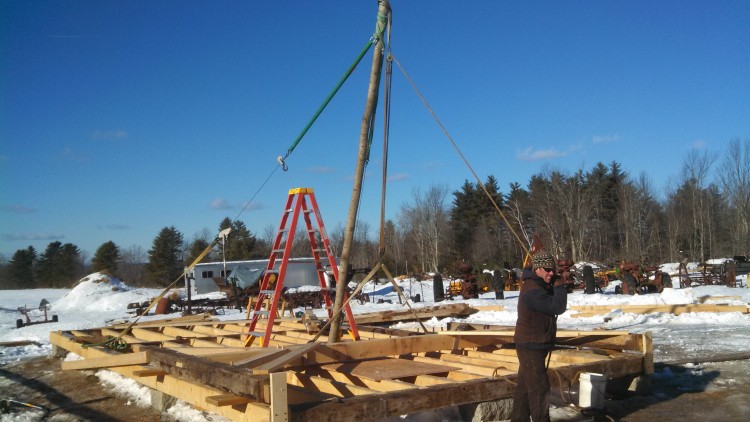
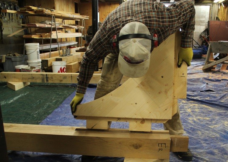
    In early August, our first task was to repair the bents. Eighteen of twenty original posts could be reused or repaired, and thirteen of the original tie girts were salvageable, most requiring face fixes to their outer ends. All of the original braces were nailed, and we replaced them throughout with mortise-and-tenoned braces. Originally, the barn contained no loft girts within the bent beneath the ties; the loft joists had rested on top of eave and drive girts. We inserted loft girts into the bents, to better connect the eave and drive posts. Each drive post was 24′ long, hand-hewn, and twisty. We used the traditional scribe rule method to install the new framing members. Using a transit, we built a level “table” on which to assemble the bents. The “table” is eleven stacks of 6″ x 7″ cribbing laid out to support the post feet, the joint between tie girt and post, the joint between tie beam and post, and the rafter apex. We laid out each post and shimmed it level. Considering the twist of the posts, we leveled by measuring off the arris. On each timber, the two best faces are established as “reference” and the corner where they intersect is called the arris. The handhewn surface may vary, but this way, our posts will still line up on the foundation. We fit the tie beams and checked measurements, squaring the bent by measuring across diagonal corners. Then we laid the new loft girts and braces out on top of the bent and used a level and combination square to scribe their shoulders to the associated post or tie girt. Not one of the original rafters could be salvaged, except maybe for use as a dugout canoe. We increased the size of the rafters to  7″ x 9″ and used string lines to scribe them to the bents. Due to the time restraint, we weren’t able to scribe the actual rafter timbers to the bents until their final fitting before crane day, and this ultimately pushed our crane day from Thursday to Friday. Next time, we’ll go slower and scribe rafters while we’re fitting the rest of the bent.

    Mortise in sill to accept twisted post

    By the time the bents were fit, the foundation was poured, and sill timbers cut. We were able to use the foundation as our “table” while we fit the eaves. This was ideal, because the drive posts could be laid directly over their granite piers. After the posts were laid out and square, the new, longer eave girts and plates were laid out and scribed. This is where the use of reference faces becomes essential. During assembly, reference face is always up. When fitting the eave walls, the reference face is 90 degrees to the reference face that was used to fit the bents. By consistently measuring and laying out the timbers to the same point along the arris, we can ensure that the eave joinery will fit tightly when the building is standing.

    Fitting the Final Rafter
    Fitting the Final Rafter

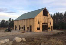
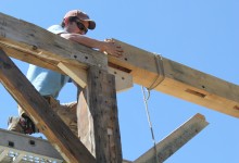
    Crane Day required the entire crew. Placing the barn on a high foundation wall meant the loft girts were high, 9′ above grade, and the plates were 7′ above that. For each timber, there needed to be a crew member on the ground and two more up high. We used blue frame staging along each eave and a scissor lift in the drive. After bent one was raised, a dozen more timbers needed to be placed (loft girts, drive girts, interior post and braces) before bent two could be flown in and connected. When the bents were all standing, the 7″ x 9″ x 25′ rafters were each flown in and fitted over the drive posts. Lastly, the crane set the purlins. It was 3:00 pm on a Friday, and they came in fast.

    Sheathing the Roof
    Sheathing the Roof

    Sheathing the roof that Monday was exhausting, the boards were hemlock, and green. But we finished with a couple days to spare. This barn has had a long life. Like marriage, it is the product of hard work, thoughtful attention, adaptation and love. We wish Charley and his bride the very best.

    Foley Horse Barn
    Foley Horse Barn, photo by Charles Foley

    For more photos, explore our Flickr album.

    Foley Horse Barn
  • Stylish Scarfs for Summer

    Stylish Scarfs for Summer

    Joe McAllister, fitting Bent 6. Welcome back, Joe!
    Joe McAllister, fitting Bent 6. Welcome back, Joe!

    On Monday, the Pennell crew erected the ell by hand. They had a roustabout on-site, which is like a more portable, telescoping gin pole, but the bents were light enough to raise with a crew of four. The ell, a drop-tie frame built in the mid-1800s, was dismantled earlier this spring during the first phase of Pennell House repair. The frame parts were transported back to the shop in Berwick, repaired, and test fit. Our most recent North Bennet Street School intern, and newest employee, Joe McAllister devoted his final school project to the cutting and joining of two additional bents to prepare the frame for re-use as a contemporary kitchen.

    East gable, dismantled
    East gable, dismantled

    Following the ell, repairs to the house were extensive. The frame was lifted on steel I-beams in order to replace the foundation and completely rebuild the undercarriage.  Seven of the eight house posts needed repairs, two of which required full replacement. The first floor studs of the north, south and east walls all required lap repair or replacement. Along the north eave, all three second floor girts and eight of their associated braces were replaced. Ultimately, the entire east gable bent was completely dismantled, repaired, and rebuilt, while the rest of the building was left standing. See “before” picture, above, and “after”, below.

    East gable attic, reassembled
    East gable attic, reassembled

    Revisiting the job-site this week, I realized that the diversity of joinery matched the broad scope of repairs. The decision to use a particular scarf, spline or lap joint is dependent on a number of factors including location, level of deterioration, difficulty of installation, historic significance, and whether or not the joint will be in tension, compression, or subject to twisting. For joinery enthusiasts, I’ve recommended Historic American Timber Joinery, by Jack Sobon, and I’ll recommend it again; it is the definitive reference manual for those pursuing traditional repair of historic timber framed buildings (I’ve linked to a PDF, if you want a hard copy, it’s worth ordering one from the Timber Framer’s Guild). On a hybrid job like this one, combining preservation, energy retrofitting and adaptive re-use, we used both traditional scarf techniques like those in Sobon’s book, and contemporary approaches, like splines and free tenons. Paradoxically, sometimes the newer repair techniques are able to preserve the most original material.

    Bladed scarf, you old so-n-so
    Bladed scarf, you old so-n-so

    If you visited our site before, job or web, you’ll know that our bladed scarf is an old standby.  It works well for post fixes, because the keys prevent the joint from slipping or twisting under outward pressure. The outward thrust of the rafters from above, in combination with the possibility of a rolled sill, and the inward tension of the tie beams and tie girts, means that a post scarf should have some means of “locking” to prevent slippage.  This could also take the form of an under-squint (see below) but in this instance, we prefer the square-bottomed keys of the bladed scarf. These multi-directional forces are what make a simple lap joint inappropriate for post repairs. We expect our repairs to last for as long as the building has already been standing. Over the course of 150 or 200 years, there may be shifting in the foundation, or deterioration in a sill, that would complicate the pressures acting on our post fix.  A bladed scarf joint is designed to withstand those forces, so that in 100 years, if a sill needs to be replaced, the post foot and associated repair can remain intact. (I hope Athena, protector of woodworkers, notices that we strive only to double the lifespan of a building, we don’t expect to triple it.)

    Halved and bladed scarf in the undercarriage
    Halved and bladed scarf in the undercarriage

    A bladed scarf is also used to repair an unsupported section of sill.  When a sill, summer beam or floor girt is supported on posts or piers, rather than a full foundation wall, it needs a repair that can support itself and prevent sagging without introducing metal brackets or plates. The introduction of big plates of metal, especially in potentially moist environments, like a basement, risks the danger of condensation and its dreaded associate, rot. While a lap joint may be sufficient for many sills, on stable, continuous foundations, the keys in a bladed scarf give it compressive strength perpendicular to the joint.

    True-Randall Tie Beams
    True-Randall Tie Beams

    In a timber under considerable tension, such as a tie beam, a bladed scarf joint may not be appropriate. The joint has considerable resistance to compression and twisting, but relies on pins and friction to prevent spreading. We’ve long used a tabled, wedged joint to prevent spreading in tie beam repairs, but at the True-Randall Farm in Montville, we encountered a stop-splayed, under-squinted and wedged scarf that had been used to extend the length of tie beams by more than ten feet. The barn was moved over a hundred years ago, and the joints had loosened, but held up considerably well under the strain of a crumbling mid-century concrete block foundation. The biggest threat to a barn’s frame is water infiltration. When tying joints fail, allowing plates and rafters to spread, roof leaks can result, leading to water infiltration that will accumulate on any available horizontal surface: plates, girts and, often, all the way to the bottom of the frame, at the sill.

    Stop-splayed, undersquinted and wedged scarf in the east gable tie girt
    Stop-splayed, undersquinted and wedged scarf in the east gable tie girt

    We used this stop-splayed, under-squinted, and wedged scarf joint to repair the east gable tie girt. The east gable bent contained two tying timbers: a tie beam above, which runs from plate to plate and required full replacement, and this tie girt, which supports the second floor joists, and is fully supported by studs from below. The under-squinting is the little angled cut two inches from the top and bottom faces of the timber; this angled cut also helps to mechanically “lock” the joint, and prevent twisting.

    Slope-shouldered and under-squinted bolster.  Note free tenon in second story girt, above.
    Slope-shouldered and under-squinted bolster. Note free tenon in second story girt, above.

    Elsewhere in the house, we found another instance of under-squinting, in a slope-shouldered bolster used to repair a post. This was a really cool fix that was probably installed sometime after a renovation that involved hacking out the interior faces of the posts, so that they wouldn’t intrude on the interior wall plane (how dowdy and old-fashioned!).

    Mortises: Exposed!
    Mortises: Exposed!

    This assault on the frame resulted in some posts being sliced in half, immodestly revealing their joinery. Unfortunately, this hackery also removed the bearing shoulder of the post which formerly supported the ends of the second story floor girts. The bolster above was installed around 100 years ago to support the end of one of these girts.

    North eave, center girt, before.
    North eave, center girt, before.

    Three second-story girts along the north eave were rotted and needed full replacement. The second floor joists fit into cogs cut into the interior faces of the girts, and stayed put during installation of the repairs. Likewise, the four north eave posts could not be moved (the east gable post was replaced in full, but needed to be installed before we replaced the girts). The conditions created by a standing frame required that we use a free tenon or spline connection to repair these elements. We cut the girt to length, shoulder to shoulder, and cut a slot in the underside of the timber the full length of the free tenon.

    Free tenon repair between girt and post. Extended mortise in post is plugged.
    Free tenon repair between girt and post. Extended mortise in post is plugged.

    We install the girt between the standing posts, and then insert a free tenon into the slot. Then we slide, or pry, the tenon laterally so that in engages with the accompanying mortise in the post. Lastly, we plug the gap that is left in the girt. In those instances where the posts are in better condition, the post mortise can be extended. The free tenon is inserted below the girt and slid up into the slot. Then the extended mortise in the post receives a plug (see above).

    Half lap, and partial bladed scarf joint
    Half lap, and partial bladed scarf joint

    Seven of the house’s eight posts required repair or replacement. In each case, we preserved as much original post material as possible, resulting in some fairly idiosyncratic fixes. In the one pictured above, an interior corner of the post had been removed in the previous “renovation” and required a slightly more complicated version of the bladed scarf joint.

    Bridled half lap repair in south plate
    Halved and bridled scarf repair in south plate

    The twin threats of squirrels and rot wreaked havoc on the east ends of the north and south plates, requiring a scarf repair for each of them.  Plates endure considerable torque, created by the outward thrust of the rafters and inward tension of the tie beams. Lee used a halved and bridled scarf on the ends of these timbers in order to retain the most material, and prevent twisting or rolling.

    Splining the ell plates
    Splining the ell plates

    The original ell plate was full length, and in good condition.  The plans required an extension of the ell by two bents to accommodate a contemporary kitchen, but we didn’t want to remove any more original material from the plate than was necessary. The plate had its own interesting joinery, worth preserving, in the form of a rabbet along the top interior edge, that caught the birdsmouth on the rafter tails. A traditional scarf joint would have required the plate to be cut back as much as two feet. Instead, Ed designed a spline-joint, that connected the original plate, the new plate extension, and the post, all in one (above).

    South eave stud repairs
    South eave stud repairs

    Three quarters of the first story studs required repair or replacement. Where feasible, we used a simple half-lap repair on the athlete’s feet of rotten studs. The half lap, instead of a full length stud replacement, allowed us to replace studs with tenons on either end, even when the stick was captured by a sill below and second-story girt above.

    Rafter foot and tie connection. This one wins worst.
    Rafter foot and tie connection. This one wins worst.

    Often, we encounter bolts and L-brackets employed to little effect. Sometimes, these metal band-aids do more harm than good, due to the introduction of large plates of metal, against which water can condense and be held against the timber, or by creating a tensive or compressive force where it does not belong. There are instances, however, where a metal bolt or bracket is the best solution. The tie beam ends at the Pennell House were one such case. Each of the 5 remaining tie beams showed various levels of rot at either end, outside of the plate and the rafters’ birdsmouth. Other than the east gable tie, none of ties were rotted enough to require a scarf repair. However, the joinery on the end of the tie, the angled cog capturing the rafter’s birdsmouth, needs to resist considerable force, especially from the rafters that carry the cupola.

    Rafter tie connection, repaired with bracket and bolt
    Rafter tie connection, repaired with bracket and bolt

    We wanted to ensure that the tie beams would continue to prevent the bottoms of the rafters from spreading. Ultimately, we used a combination of 3/4″ threaded rod, and Simpson-brand L-brackets to create an economical solution to this pervasive, but relatively minor, problem.

    Preservation work can be frustrating, because every building is unique, and every problem is interconnected with others. The lack of a universal solution makes preservation work almost as difficult to estimate as it is to execute. Fortunately, it is the very same combination of variety, unpredictability and creative problem-solving that makes this work so much fun.

    Teamwork! Look what fun Joe, Lee and Scott are having!
    Teamwork! Look at what fun Joe, Lee and Scott are having!

    For more photos of our process at Pennell; please visit our Flickr page.

  • I’ll take a Gin Pole, straight up.

    I’ll take a Gin Pole, straight up.

    Lee on Deck
    Lee on Deck

    Here’s one to please our 11-year-old selves, and the folks over at Low-Tech Magazine: we raised the Carpenter’s Shop using a gin pole.  This is a simple and traditional method for raising a timber frame by hand, and straightforward solution to a site with little crane access.  It’s constructed from a long, straight pole with a block and tackle hanging from the top, and two guy lines (in our case, come-alongs) that help to counter the weight of the pole and the timbers, and locate the posts in their mortises.

    This is an eave assembled on the deck.  A bent assembly isn't pictured, but looks similar, rotated 90 degrees
    This is an eave assembled on the deck. A bent assembly isn’t pictured, but looks similar, rotated 90 degrees

    After test-fitting the eaves, we assembled the first bent (like a bread slice of the timber frame, parallel with the gable) flat on the deck so that the post tenons were hanging over their corresponding mortises – so that, when rotated to vertical, the tenons would “tip” into their holes.  The pieces of the bent were fit together so that the tie beam was placed towards the center of the deck and all the exterior reference faces were facing up.  The bent was fit, measured, bound, remeasured, and then pinned and wedged.  Each bent has two ascending and two descending braces, creating an especially stable and sturdy frame.  What original wedges couldn’t be reused were cut from seasoned white oak.  It was satisfying to knock the wedges in tight, locking the half dovetail tenon at the end of the tie beam to the sloped shoulder of the post’s complimentary mortise.  Ah, wedged half dovetails.  We screwed stop blocks to the corners of the sill so that the post feet couldn’t slip off the deck as the bent was raised.  We also screwed two 2x8x16′ pieces of KD to the exterior face of posts, at the top of the post, so that they could be used as kickstands once the bent was nearly vertical.  That completed the first bent assembly.

    Lee cut a maple sapling that was at least 18′ long, which is half again as tall as our posts (we realized through trial and error that this could have even been a little longer, but you could realize that sooner using a physics textbook). He attached a block and tackle to the top end of the sapling (again, if one was so inclined, we could calculate the exact number of pulleys needed to create the mechanical advantage to pull the bent up using human-power, but we had a tractor, so we used the block and tackle that Lee had).  Directly beneath the block and tackle connection, we attached two 24′ come-alongs.  That completed the gin pole assembly.

    Gin Pole in Tension
    Gin Pole in Tension

    We screwed a U-shaped block to the deck at the foot of the gin pole, near the center of the frame, to keep the foot from slipping out of place.  The opposite ends of the come-longs were secured to the rear corners of the deck, so that the gin pole come-alongs and block and tackle created a peace sign on the deck (a peace sign without a circle, and with two extra long come-along legs).  Scott and I lifted the gin-pole into a nearly vertical position, while Lee loped back and forth, tightening the come-alongs as we raised the pole.  Working the come-alongs allowed Lee to center the top of the pole precisely over the bent.  When the pole was leaning forward so that the block and tackle hung directly over the center of the tie beam, Scott pulled down tight on the block and tackle, connected the hook at its base to the center of the tie beam, and pulled down on the free end of the rope (pictured above).  This created a stable triangle of opposing forces (block and tackle, come-along and come-along), securing the gin pole in place about 10 degrees from vertical.  This completed the raising of the gin pole.

    Scott pulled down on the raising rope, and, nothing happened.  If we had not had the tractor at our disposal, we would have needed a block and tackle with more pulleys, and a rope with less stretch.  As it was, we hooked that sucker up to a tractor, corrupting the purity of a hand-raising.  For shame! Anyways.  We attached the rope to the front of the tractor as high and as close to the top of the gin pole as feasible.  I reversed the tractor and lowered the arm with all the grace of Kevin Bacon in Footloose as Scott monitored the post feet and Lee let out the cable on the come-alongs, incrementally.

    First Bent, raised
    First Bent, raised

    Once the bent was lifted past 45 degrees, I set the brake, re-tied my shoelaces, and Scott and I used the 16′ pieces of KD attached to the tops of the posts to lift the bent to vertical, and seat the tenons in their mortises.  We screwed the KD kickstands into the eave sills, and stopped to admire our work. With the kickstands in place, we were able to plumb the bent precisely.  When we satisfied with the bent’s location, we moved the gin pole, and prepared to raise the second bent.

    Lee in Tee at 10 degrees
    Lee in Tee at 10 degrees

    The gin pole was not the only low tech technology employed at the Carpenter’s shop.  Lee used an adze to cut the tenons of the first floor joists, allowing him to work in a tee shirt in single digit temperatures.  After the bents were raised, we used a water level to level them.  On sunny sites, it’s sometimes easier to use a water level than a laser.  If you want to know more about either of these methods, please let me know.

    New blue water level hung at reference corner
    New blue water level hung at reference corner

    Sometimes the oldest technologies provide the best solution for the job at hand.  From wedges and ramps to pulleys, I am surprised at how right my physics teachers were about the ubiquity of simple machines.  When applied purposefully, with careful consideration, these approaches can be safer, simpler and cheaper.  While I appreciate the romance associated with historic contraptions, ultimately, romance is not the reason we employ them.  These technologies are selected when they are the most functional option for the job at hand.  We were just lucky to have some fun with them up in Poland.

    Tradition
    Tradition! – tra-di-tion!

    Completed frame
    Completed frame


  • New Castle Gaze Bo

    New Castle Gaze Bo

    In the shop, Seth fitting brace tenons
    In the shop, Seth fitting brace tenons

    Preservation in the field can take many forms.  Most of the time, preservation is the most practical and reliable answer to a client’s needs, but there are times when pure preservation isn’t feasible, or reasonable (see Demeritt-O’Kane).  The New Castle Congregational Church and gazebo offers an alternate model.  The congregation has endeavored to preserve the main body of the church, repairing the undercarriage framing, and rebuilding the foundation under the rear additions of the building.  When it came time to repair the dome topping the steeple, however, the building committee was faced with a proposal: if they allowed a cell tower to be built on top of the tower box, the cell company would pay for a new dome, in addition to monthly rent during the long-term lease.  When the congregation chose to lease the space to the cell company, the dome was replaced with a hollow, fiberglass replicate.

    Additionally, the cell company contributed to funds raised by community members for the complete restoration of the original dome.  Some of the money from the cell tower helped to pay for a custom gazebo to support the restored dome.  Its historical integrity was compromised, but at least the dome would be put to use.

    The design process was a challenge.  The building committee wanted a gazebo space that was large enough for weddings and other functions, but the original footprint of the belfry wasn’t big enough.  From a design perspective, the gazebo needed to echo the original tower trim, but not overpower it.  Due to distance and perspective, steeple cornice trim can be comically large when viewed up close; it is one of the most persistent surprises since I’ve started doing this work.  Given these restrictions, Ed and Keith designed a gazebo that honored the original craftsmanship of the dome, without distracting from the classic composition of the church.

    Frame design, shop drawings
    Frame design, shop drawings

    The preservation of the dome was completed first.  The huge, curved rafters reproduced using a Prazi beam cutter, which is a chainsaw bar and chain attached to a circular saw in place of the saw blade.  The Prazi functions like a jigsaw on steroids.  Other elements of the original framing were retained, like the struts that run diagonally from plate to mast.The gazebo’s timber frame design was ingenious.  The eight-sided structure consisted of four main bents and four diagonal plates, which overlapped and connected the main bents.

    Keith using drawknife to smooth curved brace
    Keith using drawknife to smooth curved brace

    The curved braces were cut from a solid, 3″ thick glue-up.  The curve was roughed out by the Prazi, and smoothed with a combination of drawknife, spokeshave, and sander.

    Bent Stack
    Bent Stack

    The main bents were assembled in the shop, their joints were pinned, and then stacked neatly.  They were loaded onto the trailer and driven to New Castle, where we were met by a crane.  The crane unloaded each bent from the trailer and stood the frame onto its feet already located on an octagonal concrete pad.

    Placing Bents
    Placing Bents

    As the bents were unloaded, they were braced temporarily, and capped with their respective plates, creating the alternate four faces.  Working against the crane operator’s clock, we carefully laid sleepers across the plates and tapped them into their final resting places.  Once the sleepers were placed, the crane lifted the cherry-colored dome and placed it on top.

    Tarp-tented gaze-bo
    Tarp-tented gaze-bo

    The weather in the weeks that followed started with a heat wave and finished with a week-long downpour.  When the weather threatened to derail and July 4th deadline, we opted to drape the entire structure in an improvised tarp tent.

    Cornice detail
    Cornice detail

    Under the tent, we were able to complete the cedar shingling of the skirt roof, hanging the cornice, casing the posts and braces and hanging beadboard on the ceiling.  Our friend Iain Mackenzie turned and installed a custom balustrade.  By July fourth, the tarp was removed, and New Castle was able to dedicate the gazebo on Independence Day.

    Gazebo, completed (unpainted)
    Gazebo, completed (unpainted)

    New Castle’s approach may not fit the preservation ideal, but it was a compromise that ultimately led to a new community space and the adaptive re-use of a significant architectural artifact.  See more photos in our Flickr set.

  • O’Kane Crane Day

    Yesterday was the first day we had a crane on site to help dismantle the O’Kane house frame.  I don’t think the day could have gone more smoothly, all thanks to a great crew, and crane operator Frank Donahue.

    Rigging the rafters
    Rigging the rafters

    Rafter pair, flying.
    Rafter pair, flying.

    Thank you, Kendra, for all the pictures.  Check back soon for more.

  • Coverage

    We’re building the roof that will link the belfry and clock tower, while the local media is covering the crane day, and the steeple’s connection to the community.

    Here She Comes

    Christine Parrish of The Free Press wrote one of the best articles I’ve read, she really focuses on the joinery and construction history:

    Shawn Perry, of Preservation Timber Framing, Inc., the firm that was contracted to rebuild the steeple using the original plans and traditional joinery, stuck his fist into the heart of one of the rotten steeple timbers and pulled out a fistful of sawdust.

    “How this stayed standing, I don’t know,” said Perry.

    The clock tower bears 11,000 pounds of weight, according to Perry, so each corner beam would have had to take almost 3,000 pounds of weight.

    “A storm could have toppled it,” he said… read more

    From WCSH6 of Portland

    From NECN

    “Steeple Finally Home Atop Damariscotta Baptist Church” by Alex Brodsky, Lincoln County News

  • Spire Higher

    A selection of photos from yesterday’s crane event.  Click on the photo to read a description and visit our Flickr page to see more.

  • Crane Day Tomorrow, Big Ups!

    The crane arrived today.  Tomorrow, it will lift the new belfry, bell and spire onto the clock tower .  Keeley, the crane operators, will be using the same crane and lifting from the back parking lot again, with a lot more weight in the trunk.

    As the spire has been rigged since last week (we have been looking forward to this) we spent the day with last minute preparations: collecting the clock from the library, dropping the staging around the spire, building out the staging up top and installing two more braces at the base of the clock tower.

    Join us in Damariscotta for a closer look.

  • Damariscotta Crane Day Shots

    Click on an image to read its description.

Think we can help? Get in touch.