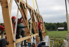
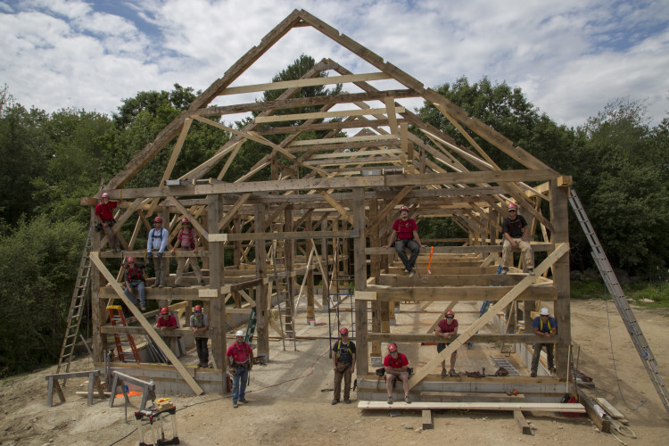
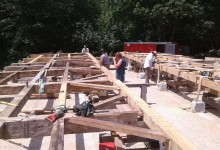
Last week, the entire crew came together to raise Arron and Michelle’s new barn. A lightning strike destroyed their home, our office, and workshop over two years ago. Last night, NewsCenterMaine published a lovely story about how the community has been helping to rebuild ever since. Arron and Michelle and all of us at PTF feel very fortunate to be surrounded by so much love and support. Thank you to all our dear friends, colleagues, and neighbors.
Thank you Alex Dykstra for taking all these great photos of the day:
Raising the front eave.Walking the eave into position.Installing the first tie beam and rafter pair.Fitting the braces.Fitting the posts.We sheathed it over the following week, and since then, the SIPs have been installed. It’s been a long wait, and we’re all relieved that it’s weather tight.Thank you everybody. We are very lucky.
Raising the right eave wall, an 8-point pick. Photo by Josh MacNally
“We have to raise Weigand by the second cutting.” To a slicker like me, Arron was exhorting the crew to finish repairs on the enormous Brasen Hill Farm barn in time for some mysterious Pagan ritual. He was right. As soon as the roof was sheathed and papered, and before it wore metal roofing or sidewall sheathing, Eleanor Kane and Theo Weigand’s crew were loading the lofts with hay. Arron loves our collaborations with farmers and is wont to wax poetic about the symbioses between traditional buildings and sustainable farming. Partly, I think he’s in it for the work ethic farming requires.
Raising the left eave wall, and Zach lugging a girt. Photo by Josh MacNally
The barn at Brasen Hill was built in the early 1800s. It’s a hewn frame, with English tying joint and gable entry. Curiously, the seven bents were referenced as if for an eave entry, although it doesn’t appear that an eave entrance was ever installed or used. The previous owner, Randy Warren, just published a memoir: 67 Years of Stewardship, The Warren Farm, A Unique Farming Story. In it, he writes of their efforts to stabilize the barn, which was sinking into the ground. Every so often, they would jack up the “interior vertical beams,” or drive posts, and pour concrete pads underneath. One year, after they released the jacks, one post just stayed up there, and the barn proceeded to twist and settle around it. We admire his efforts. It’s hard to locate the time or funds to repair a large barn, especially a working one. That hasn’t changed. See second cutting, above.
Installing a tie beam, a 4-point pick, Photo by Josh MacNally
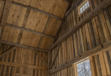
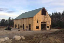
By the time PTF got to the project, the entire right eave was toast. Eight of fourteen rafters needed to be replaced, along with three of the seven tie beams, and more than half of the twenty-eight posts (interior and exterior vertical beams). We were grateful to the Weigands for their commitment to the barn, the craft embodied in its timbers and its centuries of service. The new barn already has garlic drying in its rafters. It houses a new insulated break room, with a poured concrete floor. It will house goats and sheep, chickens and turkeys. Maybe a cow. Brasen Hill Farm offers a sliding scale CSA from June to October and sells Christmas Trees in December. Their farm store is open now. The pictures don’t do it justice, go and visit!
Dan Boyle is serious. He means it. Photo by Josh MacNally
We bid a fond farewell to Josh MacNally this week. He left us with beautiful parting photos of the Brasen Hill raising and finished barn. Thanks for all the hard work, Josh!
Contented crew after a long crane day. Photo by Josh MacNallyBig barn from the hay loft. Photo by Josh MacNallyInterior Vertical Beam foot fix (all the drive posts got ’em). Photo by Josh MacNallyBladed scarf joint over eave post. Photo by Josh MacNallyWe installed two new staircases for better access to the lofts. Photo by Josh MacNallyA reclaimed roof system. Photo by Josh MacNallyFinished product, with three new sliding woman doors. Photo by Josh MacNally
For more photos, peruse our Flickr album. Thanks, everybody! But especially David Ewing and Dan Boyle.
Hey, real quick! We’ve been cutting scarf fixes for enormous post feet, and fitting teleport pads for octagonal lanterns. Updates on Chestnut St Lantern, Brasen Hill Barn, and Jennison Barn, below.
Teleport Pad, Photo by Jacob Imlay
Chestnut St Church Lantern, Camden, ME: This cute little lantern was cut and fit at the shop, and is ready for transport to the Lyman-Morse boat shop later this week. There it will be fit with a 50-foot fiberglass spire and four 7-foot half-round hoods. Jake laid out the frame and Tim, Zach and Charlie cut and fit the joinery. Zach’s experience building guitars and Tim’s experience making furniture helped maintain tight tolerances. The entire lantern and spire will be laid down on a low-riding flatbed for final transport to the church, where a crane will tip the entire assembly up vertical. It is important that the joinery is tight in order to withstand the torque and lateral loads. Scott, Tim and Arron worked with Taylor-made builders up in Camden to plumb the tower and repair the belfry post feet at the Chestnut St Church. More about removing the old spire, here.
Lady Lantern, photo by Jacob Imlay
Brasen Hill Barn, Barrington, NH: Led by Dave and Dan, the rest of the crew have been busy with an enormous barn restoration at Brazen Hill Farm. The barn is beautifully hewn, with drive posts like tree trunks. The deterioration was extensive and the barn was completely dismantled for repairs. The extent of rot meant that the barn was heavily braced and was disassembled piece by piece by a crew of eight over two days.
Brasen Barn from above, photo by Josh McNally
Dave, Dan, Tom, Byam and Michael have been busy making traditional timber frame repairs at our shop in Nottingham, NH. Given the extent of damage, the crew worked hard to preserve any viable original material. That means a lot of dutchman and post feet fixes. Dan Boyle documented the repair and fitting process. A few of his process photos, below.
Undersquinted face fix, photo by Dan Boyle
An under-squinted dutchman repair can be used to repair the cheek of a mortise where a pin has blown out the relish. The rest of the post was in good condition and of a dimension and quality that is difficult (but not impossible) to find today.
Get (in the) Bent Brian, photo by Dan Boyle
After the rotten timbers are repaired or reproduced, we use come-alongs to pull the joinery tight and the bent square. Then we drill holes for the 1-inch oak pins that will hold the joinery together.
Eave fitting, photo by Dan Boyle
The barn is big, almost 70-feet long and 40-feet wide. It contains seven bents. The finished frame was raised almost a month ago, and Dave and Scott documented the process by helmet-cam. Stay tuned for the movie.
Jennison Barn, photo by Josh McNally
Jennison Barn, Lee, NH: New Hampshire Preservation Alliance has featured the Jennison Barn as one of their 52 barns in 52 weeks. The NHPA article captures why preservation is important on a human scale, from families to communities. Read their story, here.
We all have illusions about longevity. Many people think that a building’s strength is derived from its foundation, made of stone, or brick, or concrete, but that’s only partly true. A good foundation is a blessing, but a bad foundation is not damning. We’ve seen so many foundation failures that in a well-designed timber frame, we consider the foundation a sacrificial element.
The Lord Barn is one such example. Over the past decade, the barn had emulated a pat of butter on hot toast. Its fieldstone foundation was slipping, and the eave sills had rolled out from under the plates. The building looked dangerous to teenagers. With this kind of failure, we expected to find a lot of rot. But with the corrugated metal roof and deep overhangs, water infiltration was never the main problem. There was plenty of air flow, so bulk moisture wasn’t being trapped inside the building. While the foundation and undercarriage melted into the ground, the timbers above stolidly endured.
Lord Barn plate-to-post connection.
Dating a barn like this is hard, and not just because it’s a hot mess. Many of the larger beams, the tie beams, rafters, plates, and posts, are hewn, which means that their surface was smoothed with an adze or broadaxe, resulting in a texture like hammered copper. Hewing was replaced by up-and-down milling throughout the 19th century, depending upon proximity to a sawmill, and frugality. But the frame design and joinery of the Lord Barn follow later trends, especially the plate/post connection. The plates are discontinuous, and are joined into a mortise at the top of each post. The end of the plate rests on a 1″ let-in, or shoulder, characteristic of square-rule joinery, which became popular in the late 19th-century. Hewing is a labor-intensive and thoroughly handmade practice, while square-rule framing, although also cut by hand, was an innovation in efficiency that made pieces more uniform and interchangeable.
Lord Barn, principal rafter-principal purlin roof, with stacked common rafters.
Both gable ends have integrated pocket doors, where the door slides through the middle of a 12″ deep post. Pocket doors look slick, but aren’t suited to this climate; the door and post expand and contract, and the gable sill isn’t well-protected. Arron says Tom Visser’s field guide dates interior pocket doors between 1870-1880, but I can’t find the book to quote it directly, so.
Lord Barn, Rafter-Tie Beam joint
The roof system, with common rafters stacked over a principal rafter-principal purlin frame, is 1870s’ish. The common rafters are sawn and relatively small, 3″ x 5″. By stacking them over the purlins, the major roof framing is better protected. The rafters join the tie beam well inboard of the end of the tie, which means more material in the tie is resisting the outward thrust of the rafters. There is also better airflow around the principal rafters and purlins. In the Lord Barn, the common rafters run well past the plate, creating a deep overhang, which protected the sidewall framing as the sills slid and spread. The frame’s design brackets this barn between 1860-1880. We think it is a late example of a totally hewn frame.
Lord Barn overhang
When the foundation failed, the joinery was put into tension. In a pinned mortise and tenon joint, the pin prevents the joint from separating as the building settles and moves. But it doesn’t matter how strong the oak pin is once the relish past the pin hole gives way. In places where the joinery failed, tenon relish was the culprit.
Lord Barn, post-top tenon relish failure
The left eave sill rolled right off the foundation, pulling many of the left eave posts with it. It racked the entire frame, the posts pulling away from the loft girts. The tenon relish, just past the pinhole, was sheared in nearly every loft girt, and in many of the post tops, too. In bents where the post-tie beam connection held strong, the end of the tie beam dropped dramatically away from the rafter.
Lord Barn, rafter-tie beam separation
A year ago, we disassembled the barn with the entire crew. The clients, Pat and Paul Boisvert and Linda and Frank Underwood, de-nailed the timbers and helped dismantle the bents once they were on the ground.
Paul and Frank pull sheathing while Pat and Linda de-nail studs.
Over the course of the summer, the clients had the foundation poured and built the floor system themselves. In the Fall, PTF made the few necessary repairs to the frame which included small repairs to a few post feet, and some face fixes where the pin had checked the cheek of a post or tie beam.
Third H flying in, photo by Joshua McNally, jamcnally.com
Almost exactly a year later, the whole crew came together again with the clients to re-erect the frame. Because of the discontinuous plates, a frame like this needs a lot of hands on crane day. We assembled each bent into two “H’s” on either side of the drive, with an eave post, a drive post and a loft girt. There were five bents and ten “H’s”.
Arron signals the crane operator as he places the “H”. Photo by Joshua McNally, jamcnally.com
We started in the left side aisle. The crane lifted the left rearmost “H”, and the crew stabilized it with a KD kickstand. Then two loft girts were installed, perpendicular with the first “H” and propped up with temporary deadmen. The second “H” was stood up by the crane and we worked in two teams of three to engage the loft girts. Two additional people on rolling staging lifted the plate and inserted it between the two eave posts.
Engaging the fourth H with the plate. Photo Joshua McNally, jamcnally.com
When the first two “H’s” were plumb, all the joints were temporarily secured with KD gussets. At this point, the box was relatively stable, and we moved onto the third “H”. After the left side aisle was completed, we repeated the process in the right side aisle.
The crane operator flies a purlin to Dan. Photo by Joshua McNally, jamcnally.com
After a late lunch, the crane began flying in the upper triangles formed by the tie beam and rafters. The installation was complicated because the bottom of the tie beam needed to engage with four posts and four braces. Over time, a few of the tie beams had bent to conform to the drooping left eave, and each tie beam fit with some idiosyncrasy. Additionally, there was a pinned purlin between each pair of rafters. These beams needed to be installed by crew-members on staging at roof height. Before each tie triangle was flown, two staging towers needed to be dismantled and re-erected in the subsequent bay in order for us to be able to install those principal purlins. Every member of the crew and each of the clients were needed to erect the frame in a single crane day. It was a lot of fun.
Lord Barn Frame, Re-erected, Photo by Joshus McNally, jamcnally.com
Ultimately, the frame was saved, but the foundation was a lost cause. The relative flexibility of timbers and the strength of their joinery often allows them to outlast their granite and fieldstone foundations.
Crane Day crew, photo by Joshua McNally, jamcnally.com
Our newest crew member, Joshua McNally, took a bunch more lovely photos of our crane day and of the Lord Barn after the roof was sheathed. For more, photos, explore our Flickr album.
I write a lot about our unusual jobs: a deserted island, an elevated dance floor, or a building-sized jewelry box, but most of us got into this to do jobs like the Jennison barn. The job incorporates so many of PTF’s defining motifs: barn preservation, adaptive re-use, local history and creative clients. The Jennisons called in early 2015 about a barn that had collapsed under extreme snow loads. After assessing the damage to the frame, and a long period of negotiation with the insurance company, we concluded that the barn was not salvageable, and that its replacement would need to be significantly scaled down. Ultimately, too many of the posts had snapped in the collapse, and the replacement coverage did not include the embodied value of the craftmanship and timber joinery. Fortunately, PTF had dismantled a smaller frame the previous year, and had hoped we could find it a home nearby.
Brock standing
Brock’s Barn was located at Brock’s Crossing in South Berwick, near Slut’s Corner (the etymology of “slut” is facinating!). Simeon Brock bought the farm in 1790 and lived there with his wife, Judith, and their five children until his death in 1814. None of the children married or moved from the property. The youngest, Deborah, began working for the Portsmouth Manufacturing Company when she was 23. She was known for walking the mile and a half commute to the textile mill and for her thrift. Deborah managed the farm until she died in 1883 at the age of 74.*
Two barns in one, 18′ x 18′ extension on the left, 28′ x 42′ on the right
The Brock barn was actually two barns in one. A smaller, earlier 18′ x 18′ frame was expanded with a 28′ x 42′ frame. The rafters and ties of the former were extended to match the dimensions of the latter. Above, you can see the two adjacent posts where the gable ends of the frames meet. The 18′ x 18′ frame appears to have been built earlier, as the joinery was clearly retrofitted to expand the footprint and raise the peak to match the larger frame.
18 x 18 barn, original roof framing lower right. The ridge was raised, and roof plane extended.
Both frames have hewn timbers and scribed joints. Both frames exhibit the English tying joint, where the plate crosses over the post, parallel with the eave, and the tie beam crosses over the top of the plate. The interior face of the post, about half its thickness, extends past the plate to join to the tie beam with a teasel tenon. Both frames are eave entry, which was an earlier, “English”, floor plan. Both frames are early enough that it is difficult to date them definitively. The larger frame has up and down sawn braces, some of which exhibit the natural curvature of the limb, as above, but this does not date it. The first saw mill to operate on the neighboring falls was established in 1634. The 28′ x 42′ frame is also distinguished by much larger timbers, especially the lower tying girt and longer braces. Based on framing methods alone, it could have been constructed anywhere between 1790 – 1840.
English tying joint joins post top to plate and tie beam
Given the history of the property and surrounding town, we suspect that the 18′ x 18′ barn was built at the time Simeon bought the property in 1790. The smaller frame may have preceded the Brocks, but the only evidence is that they so drastically altered it. The 28′ x 42′ frame may have been built towards the end of Simeon’s life and appended to the smaller frame without any retrofit. The craftsmanship of the alterations to the 18′ x 18′ is significantly later and of lower quality than either barn frame. Some time after Simeon’s death, one of his children or one of Deborah’s farm hands may have extended the barn across the gable, and raised the ridge height. These are the histories we write as we repair the frame, fine-tuning each tenon and scarf joint.
Post scarfs on parade, photo by Dave Ewing
The Jennisons bought the 28′ x 42′ frame. Dave, Tom and Dan performed the frame repairs, and the results are stunning. Standing, the barn is defined by its array of post repairs. Each scarf joint was designed to maximize the preservation of original wood, and withstand the array of forces endured by each post. They planed the new timbers and fared their edges to blend seamlessly with the old.
Bent assembly, photo by Dave Ewing
Dave enjoyed the opportunity to work consistently on timber frame repairs. Nearly the entire roof system was in good shape, and he said, “getting to preserve that was a joy.” He also thinks that part of the reason the rebuilt barn looks so good is that all the new timber ended up in the same quadrant of the barn, in the new loft. The crew repaired the barn in our shop in Nottingham, NH and fit the bents together inside the shop. Then they disassembled the frame and transported it to its new home in Lee. Nearly the whole crew attended the raising, and both Seths and Brian assisted with the finish.
Jennison Barn, rebuilt. Photo by Josh McNally
Charlie Jennison plays saxophone and teaches music at Exeter Academy and UNH. He wants to the barn to serve as a concert space, and we hear that they’re already hosting successful events. Along with the outdoor sculpture gallery across the street, the Jennisons are creating an art enclave in Lee, and we’re proud that the barn gets to be a part of that.
The following photos of the finished Jennison Barn are by Josh McNally. Visit our Flickr page to see photos of the two frames before they were dismantled. Brock’s 18′ x 18′ frame is dismantled and looking for a good home.
Over New Years, my intentional friend likes us to sit in a big group and practice “Rose, Thorn and Rosebud.” We say the best thing that happened to us this past year, and the worst, and the thing that we’re looking forward to in the coming year. My rose took so much time that it’s been nearly absent from the blog, but it’s an easy pick: the completion of the Hampton Town Clock Tower. (This is me talking for me, Arron would surely have a harder time choosing. There’s the completion of the first phase of Wood Island, the East Derry undercarriage, Northwood Church and Jennison barn. There’s the installation of the trusses at Troy, and the commencement of undercarriage repairs in Readfield. There’s the long-awaited restoration of the windows in the converted barn that serves as our office, shop and home for Michelle and Arron. Scott Lewis returned to PTF to be our Project Manager, a top contender for blue ribbon). My thorn was losing Joe McAllister to the wilds of Minnesota; I hope his rose was one of projects that he’s since completed out that way.
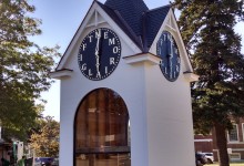
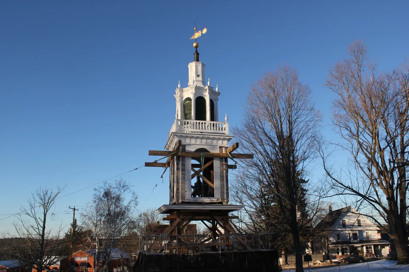
Hampton Town Clock Tower stands out because it wasn’t the typical repair fare. Instead of repairing a historic building, we re-interpreted one. In 1990, a catastrophic fire destroyed the Odd Fellows Building in Hampton, NH. The only artifact that could be saved was the Hampton Town Clock, and that had been warped by the intense heat. The clock was given to the town by John T. Brown in 1897, with a dial which spelled out “M E M O R I A L G I F T” in place of numerals so that every person who wonders why it’s half past “G” remembers his generosity. Since 2004, a dedicated group of Hamptonians have been working to restore the clock. They wanted the clockworks itself to be on display, in a housing that referenced its original home.
Most people think of a clock as a round face with hands and numbers, but a tower clock is the size of a sideboard, with large bronze gears and a 9′ pendulum that swings below it. The round face is called a dial and might be the least interesting part of the whole contraption. Hampton’s clock is a Howard Round top, which means that the gears sit between two half-round carriages, about 4′ wide, 4′ high, and 2′ deep.
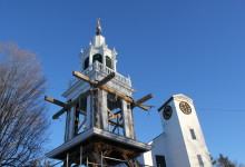
The original tower, built in 1895, was too small for the clock, and was raised twelve feet and rebuilt in 1897. The roof was unique, with cross gable pitches topped by a spire reminiscent of a witch’s hat. The roof and dials perched above a belfry with large open arches on each face, and pilasters on each corner. The committee wanted us to build a standalone clock tower that displayed the clockworks at eye level, referenced the original building, and fit into their budget of just under $100,000. We also learned that the clock would work best if the bell was located beneath it, so that the drive train could be relatively straight, and not be diverted around a large bell. This created our biggest design challenge. We wanted to display the clockworks at eye level, but the clock needed to be located above a bell that stands 5′ high in it’s carriage.
Tower and staging
At first we designed a building that nearly reproduced the belfry, with its open arches and fluted pilasters. We kept the original gables, but eliminated the witch’s hat. We presented the project at the Crit night of the Portland Society of Architects to get their input on the arrangement of clockworks and bell, and ended up getting better feedback about the roof and trim. They encouraged keeping the original roofline and accentuating the timber frame. We learned from the committee that the pilasters didn’t fit into the budget anyway. Ultimately, we arrived at a design that replicated the iconic roofline, over a much simpler box. We enlarged the arches, which echo the round top of the clock, but lost most of the Victorian trim, which took the focus away from the main object anyways. The timber framed floor hovers just above the bell, and is cut away at either window, so that the view of the clock is obscured as little as possible. The bottom of the clock is directly at eye level, so that visitors look up into its workings. One of the architects dismissed the design as looking like a ticket kiosk, which was OK by us, but I think of it as a building-sized display case for a desk-sized clock. The design process was incredibly rewarding, and the inputs from each stakeholder and committee member improved the design. Together we created a building that better fulfills its purpose than we could have on our own.
Slated Roof
Lee Hoagland, Jake Imlay and I cut and fit the frame at the shop. The new clocktower would be erected on the front lawn of the Centre School in Hampton, and we needed to complete as much offsite work as possible before we could work onsite during summer vacation. The foundation and site work was donated by Kenny Lessard by the end of the school year, and we erected the frame in early July. With Scott Lewis and Seth Rowell’s help, we sheathed the building and completed the trim. Portland Glass manufactured and installed the 10′ high arch-framed windows, many thanks to Paul Vermette and his crew. Skip Heal of Northeast Lantern donated a reproduction of the elaborate wind directional. The Heritage Company graciously accommodated our tight timeline and slated the eight peaks and eight valleys in August. In November, the clock was installed and running and we celebrated with the community, including many residents who fondly remembered the original tower and the clock’s tolling.
Hampton Town Clock Tow
While I certainly hope for more new design-build jobs in 2017, my “rosebud” for the coming year is the work we are doing with communities throughout Northern New England to preserve their historic landmarks, and that was the real pleasure of Hampton. We will be collaborating with local contractors in Troy, Readfield and Eastport in the Acworth Model to develop repair plans and share specialized skills. From the committee chair to the on-site carpenter, we are fortunate to work with folks who really care about their neighbors. We work with people who donate a lot of time, knowledge and money to a communal cause: saving the structures that serve as a reminder of our shared history and as meeting places that knit the community together.
The Winter Street Church Sanctuary, before remediation.
(Hey readers, this was a cool job we completed over the summer, and Jake Imlay wrote up a nice blog post about it. Enjoy!)
The Winter Street Center in Bath ME, home of Sagadahoc Preservation Inc., is striking at first glance. Sitting near the top of a hill, its gleaming white tower is outlined sharply against a blue sky. The tower is three tiered and ornamented in a Gothic revival style, with layers of pointed arches and slender spires topped with carved finials that look like spring onions. The building is flush board sided and bright white except for the window trim, which is red. The windows are triple hung and topped with a fourth fixed sash shaped into a pointed Gothic arch. On the whole, the simple strong lines of a New England church in white, and the more pronounced Gothic revival ornamentation work well together and the building manages to be eye-catching while fitting comfortably into its surroundings.
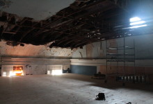
Inside, the main sanctuary space is defined by subtle curves. The balcony wall is curved, along with the narthex wall below it, and the ceiling has, or had, a deep cove. The narthex wall is the wall separating the front entrance, or narthex, from the sanctuary, and often offers structural support to a tower. This wall is where the curves originate. The sanctuary is close to 40 feet across and the curve starts at one wall and swings to the other catching the back center of the room at its deepest part. The pews mirror the curve as they move towards the altar as does the back portion of the balcony that wraps around three sides of the room. The last place the curve repeats is in the ceiling in an arch spreading from wall to wall. It was this ceiling and its spectacular failure that brought us onto the project.
During a windstorm in August of last year, about a third of the plaster and lath detached itself in one huge sheet and came crashing down onto the pews below. The reasons for this are not entirely apparent, but the plaster ceiling is/was attached to a surprisingly slight structure of 1” thick pine boards suspended from the roof trusses. The one inch thick boards are widely spaced and the edges provide by a very small amount of fastening surface for the lath. It may also have had something to do with the family of raccoons living in the space above the ceiling. The combination of weather, light framing and furry squatters proved disastrous.
Sagadahoc elevated timber deck, partially erected
We worked with EnviroVantage to clean the ceiling off the pews and erected a semi-permanent timber-framed platform from which they can demolish the remaining plaster and lath. The floor will pass over the balcony pews and land about 10 feet below the highest point of what remains of the arch. After the demo is completed, we’ll address structural issues in the roof trusses, and rethink the ceiling framing that defines the arch.
Sanctuary interior iso
The timber framed platform was conceived as a cost effective alternative to a more traditional staging setup due to the point loads in the basement, the nine foot cantilever over the balcony and and the amount of time it is going to have to be in place. Usually, it’s more economical and efficient to rent ringlock staging than to timber frame our own, but the timeframe for this repair is on the order of years not months. SPI was facing the rental of a lot of staging for several years or paying to erect and disassemble a lot of staging several times. The timber frame will result in fewer penetrations of the original sanctuary fabric, point load directly to ground and result in a work surface that is inherently stronger and easier to work off of than temporary scaffolding. The timber floor solution will allow the abatement crew to remove the remaining ceiling from rolling staging.
Timber frame floor, from below
The elevated floor is supported by four timber frame walls, consisting of seven posts, with paired braces and topped by a 60′ scarf-joined plate. The four plates are spanned by engineered I-joists, which pass over the balcony and rest on a knee wall adjacent the exterior eave walls. The biggest challenge in installing the timber frame floor was cutting the posts to the correct height. The tops of the posts needed to be level with one another for the joinery to fit, and the floor needed to be level in order to accommodate rolling baker’s staging. The main sanctuary floor rests on a series of six carrying timbers that run from eave to eave and the widely, unevenly spaced joists between them. The height of the sanctuary floor varies by more than two inches. We first mapped the carrying timbers in order to locate the posts directly over the carrying timbers, and to ensure the the carrying timber was supported by a pier directly beneath each post. We cut the joinery for the entire floor leaving the ends of the posts long. Once on site, we strung level lines across the sanctuary at the height of the elevated floor and parallel with the carrying timbers and measured down from the lines to the floor. The joinery was cut uniformly, but each post was custom cut to length. We were very pleased with how the joinery came together. If you want to see the plans, check out the Sagadahoc conceptual drawings. Sagadahoc Preservation Inc. is currently fundraising to restore their historic sanctuary, find out more or donate here.
The First Parish Meetinghouse of East Derry, NH is preparing for a big anniversary, its tricentennial. What does one even get for a church on its 300th? Wood? Copper? Both, as it turns out. Beginning with a thorough assessment and rehabilitation plan in 2011, the congregation has been working steadily to repair extensive damage throughout the steeple and undercarriage. This past fall, we extracted the belfry and lanterns from the steeple stack. After the new year, we documented the upper sections from a woman-lift and dismantled them from finish to frame.
Lower lantern roof, crowned with urns
As we surgically removed trim, we encountered earlier salvage efforts. Dan and Rod peeled back the gracefully curved roof between the upper and lower lanterns and revealed an oiled sailcloth roofing. The sheathing below was labeled November 1916.
Lower Lantern Posts
The frame was in far worse shape than we expected. Years of roof leaks and patchy repairs had finally overtaken the stout timbers. Once the lower lantern posts were exposed, we wondered how the structure was still standing and realized too late the bravery of dismantling it. Above, you can see that the six of the eight posts were hollow or non-existent at the top. An extensive repair campaign in the 1990s consisted of bolting channel steel and L-brackets to the crossing crab members (a “crab” is a horizontal web of timbers that spans the posts of a lower level and support inboard posts above). Looking at this picture, stiffening the crab fell far from the root of the problem.
Lower lantern crab above belfry ceiling
The crew struggled to free the timbers from their steel cages only to discover a corpse. It’s tragic that this rot wasn’t addressed when the church raised money for its repair two decades ago. A comprehensive, traditional approach at that time would have prevented the wholesale replacement necessary today.
Truss spread
In 1719, Scotch-Irish immigrants, fleeing religious persecution in Northern Ireland, settled the area that became East Derry. In 1722, they built their first meetinghouse on this site. The present structure was built in 1769. By its centennial, in 1822, the congregation had so grown that they cleaved the building in two and dragged one end 24 feet to the east. Above, you can see the first additional bay, indicated by the absent strainer beam and braces.
East Derry Wall D
In our assessment drawing above, the strainers and bracing between the trussses in bents 3 and 4 and bents 5 and 6 are non-typical. The strainers and bracing in bright green are non-existent; that is the bay in the photograph above. The yellow strainers and bracing between bents 5 and 6 do not quite reach bent 5, they are connected by a series of sisters and scabs. The evidence in the frame complies with the history: our hypothesis is that in 1822 the building was split between bents 3 and 6, (originally bents 3 and 4). Bents 6 through 9 were dragged to their current position, and bents 4 and 5 were built as exact reproductions of the originals. The strainer and braces that used to connect bent 6 (originally 4) to bent 3 were sistered to bent 5, and the strainer between bents 3 and 4 was deemed unnecessary. We are curious to uncover more of the eave wall framing, specifically the plates and the sill scarfs, to see whether there is more evidence to support our theory.
Parallel rafter chord truss
The East Derry First Parish truss is iconic. It has a king post in the center, with parallel rafter-chords and crossing pairs of ascending and descending struts. The king post is in tension, picking up the tie beam at the middle of its span, and the ascending struts rise from the king post and prevent the rafter from sagging. In the Timber Framing series, “Historic American Roof Trusses,” Jan Lewandowski explains:
Outward pressure on the walls can be eliminated entirely by affixing the feet of each rafter couple to their own tie beam. The problem of sag can then be addressed by hanging a joggled vertical member, or kingpost, from these rafters and using it in tension to support the midspan of the tie beam… By a less obvious intuitive leap, it might be realized that the midspan of the long rafters can be kept from bending by struts rising from lower joggles on the suspended kingpost.
East Derry Bents 1-4
The parallel rafter-chord is an innovation that protects the Achille’s heel of the king post truss. The casual observer often assumes that the joint between tie and king post is where we would most frequently see failure over time. I’ve seen many iron stirrups that attest to the builder’s concern for this joint. But most trusses fail at the rafter heel, where the upper rafter-chord intersects the tie beam. Of this foot joint, Lewandowski writes:
Those we can inspect seem more prone to failure and impairment than most other connections in the truss, for a combination of reasons: the lack of relish beyond the mortise and the large forces involved, coupled with the low angle of attack of rafter to tie, all exacerbated by a high incidence of leaky eaves. The significance of the roof slope is that the geometry of low-pitch roofs channels more horizontal force against potential long-grain shear failure in the tie at the foot joint than it does comparable vertical breakout load on the kingpost at the peak (see TF 72, 19). The point: on both empirical and theoretical grounds, the principal rafter-to-tie beam joint is the likely weak sister in the mix.
In Sedgwick, we saw the foot of the upper chord shear a 2″ x 12″ x 22″ block clear off the end of the tie beam (It was about the size of a hefty wedding-present-breadboard). With a parallel rafter-chord truss, the duties of principal rafter and upper chord are separated. The principal rafter, the top angled timber, carries the roof, while the upper chord, the inner angled timber, carries the compressive loads created by the truss. The upper chord intersects the tie beam farther from the end of the beam, thereby protecting the relish just past the joint from shear. We so liked this truss that we reproduced it in a building where it will be on grand display: the Lewis Conservation Center.
Steeple extracted
Paul Lindemann, East Derry historian and devoted parishioner, keeps a detailed website documenting the history of the church and their repair process. The Nutfield History blog is a fascinating read for anyone interested in New Hampshire history or building history in general. The blog also benefits from Lindemann’s web design skills, something that doesn’t always attend the dual callings of historian and parishioner.
The vigor and ingenuity of the immigrants who built this Meetinghouse is evident in its frame. We honor their labor with our efforts to preserve it. In 300 years, what will historians write about the immigrants seeking refuge in the United States today?
The client’s wedding was in a week, and the barn in which he’d marry was in pieces on the ground. It was crane day, and a Friday, two things that don’t usually go together. In the worst case, a crane day on Friday means you don’t have an additional weekday in case you hit a bad snag; in the best case, it means the crane operator wants to get home, and the roof frame flies in fast and loose. In a week we’d complete a job started almost exactly four years earlier. Back then, Arron was patrolling the net, looking for a barn in need of saving, and spotted a damsel in West Poland, ME. That Saturday, he dragged his teen-aged son with him to visit the barn and get some driving practice. The frame was for sale, but not the land beneath it. It would need to be documented, disassembled, repaired and rebuilt elsewhere. When Arron arrived, another potential buyer was already poking around.
Before (September 2011)
Arron wanted to repair the barn, but needed a buyer; Charley wanted the barn, but needed someone to repair it. It was a good match. Since then, PTF has embarked upon a number of projects with Charley, most notably the disassembly, repair and rebuild of his Carpenter’s Shop two winters ago. The West Poland barn was neatly stacked in a Dairy barn at his home, awaiting its turn on a long to-do list. This fall, as Arron’s son prepared for his sophomore year in college, PTF erected a barn that had spent four years being designed and refined in Charley’s head.
Barn Frame Iso with transparent grade
Charley needs the barn to house his three draft horses, donkey and a flock of sheep. The draft horses wouldn’t fit under the barn’s original girts, 6′ 4″ above the sills, about 6 inches shorter than your standard doorway. He designed a foundation that raised the posts 2′ 8″ above grade, creating 9′ of clearance for the horses. The perimeter posts are each tenoned into a sill, which rests on a foundation wall. Each drive post lands directly on a 8″ x 8″ granite pier. Precisely 7′ tall, the piers rest directly on two longitudinal footers, 4′ below grade. A frost wall was poured between the posts; it’s top level with grade. Each post is point loaded upon a foundation wall that extends below the frost line and rests on a connected footer. This will prevent the posts from moving due to annual freeze and thaw. Ensuring that each drive post landed on its granite post required precise cutting, measuring and measuring again.
The barn we took down was built in the mid-19th century; it has hewn posts and both sawn and hewn girts. The center drive posts are more than 24′ tall, and are joined directly to the rafters. The ties are discontinuous, the outer tie mortises over the eave post, and tenons into the drive post. The plate is also discontinuous and is dropped eight inches below the top of the post. The original barn was almost square in plan, 38′ x 39′. With all that livestock, Charley needed larger bays, and decided to extend the length of each bay from 9′ to over 13′; the rebuilt barn is 38′ x 56′.
Tie Girt Scarf Fix
In early August, our first task was to repair the bents. Eighteen of twenty original posts could be reused or repaired, and thirteen of the original tie girts were salvageable, most requiring face fixes to their outer ends. All of the original braces were nailed, and we replaced them throughout with mortise-and-tenoned braces. Originally, the barn contained no loft girts within the bent beneath the ties; the loft joists had rested on top of eave and drive girts. We inserted loft girts into the bents, to better connect the eave and drive posts. Each drive post was 24′ long, hand-hewn, and twisty. We used the traditional scribe rule method to install the new framing members. Using a transit, we built a level “table” on which to assemble the bents. The “table” is eleven stacks of 6″ x 7″ cribbing laid out to support the post feet, the joint between tie girt and post, the joint between tie beam and post, and the rafter apex. We laid out each post and shimmed it level. Considering the twist of the posts, we leveled by measuring off the arris. On each timber, the two best faces are established as “reference” and the corner where they intersect is called the arris. The handhewn surface may vary, but this way, our posts will still line up on the foundation. We fit the tie beams and checked measurements, squaring the bent by measuring across diagonal corners. Then we laid the new loft girts and braces out on top of the bent and used a level and combination square to scribe their shoulders to the associated post or tie girt. Not one of the original rafters could be salvaged, except maybe for use as a dugout canoe. We increased the size of the rafters to 7″ x 9″ and used string lines to scribe them to the bents. Due to the time restraint, we weren’t able to scribe the actual rafter timbers to the bents until their final fitting before crane day, and this ultimately pushed our crane day from Thursday to Friday. Next time, we’ll go slower and scribe rafters while we’re fitting the rest of the bent.
Mortise in sill to accept twisted post
By the time the bents were fit, the foundation was poured, and sill timbers cut. We were able to use the foundation as our “table” while we fit the eaves. This was ideal, because the drive posts could be laid directly over their granite piers. After the posts were laid out and square, the new, longer eave girts and plates were laid out and scribed. This is where the use of reference faces becomes essential. During assembly, reference face is always up. When fitting the eave walls, the reference face is 90 degrees to the reference face that was used to fit the bents. By consistently measuring and laying out the timbers to the same point along the arris, we can ensure that the eave joinery will fit tightly when the building is standing.
Fitting the Final Rafter
Crane Day required the entire crew. Placing the barn on a high foundation wall meant the loft girts were high, 9′ above grade, and the plates were 7′ above that. For each timber, there needed to be a crew member on the ground and two more up high. We used blue frame staging along each eave and a scissor lift in the drive. After bent one was raised, a dozen more timbers needed to be placed (loft girts, drive girts, interior post and braces) before bent two could be flown in and connected. When the bents were all standing, the 7″ x 9″ x 25′ rafters were each flown in and fitted over the drive posts. Lastly, the crane set the purlins. It was 3:00 pm on a Friday, and they came in fast.
Sheathing the Roof
Sheathing the roof that Monday was exhausting, the boards were hemlock, and green. But we finished with a couple days to spare. This barn has had a long life. Like marriage, it is the product of hard work, thoughtful attention, adaptation and love. We wish Charley and his bride the very best.
Installing meetinghouse truss on crane day. One of many (cranes days, and trusses)
The Lewis Conservation Center will be made up of five connected timber frames, a “Big House, Little House, Back House, Barn” where the Big House is a reproduction of the 1722 East Derry Meetinghouse. One frame, the Gallery, re-uses the Green Barn, a scribe rule frame from the 1740s. The Education frame has the same exterior dimensions as the Gallery, but the interior has an open plan and a king post truss system. Similarly,the roof of the Meditation frame is supported by a king post truss, but with studded gable ends, and additional office space. The fifth frame, the Porch, is a relatively small frame, exposed to the weather, and constructed entirely in white oak. This is a big project, with a tight timeline. The frames are also mostly reproductions, built from new wood, which created opportunities to increase efficiency. Throughout the LewCon frame we used one efficient technique that we rarely find in old barns and churches. It’s called housing.
Green Barn, with Education king post truss, behind
The Green Barn determined the patina and surface pattern of the rest of the frames. The frame was hewn with adze and broadaxe, which gives the timbers a surface texture like hammered copper. They’ve patinaed to a silvery brown. The frame was cut with scribe-ruled, which is the method PTF must use for most in-kind repairs. In cutting a scribe rule, the framer arranges the timbers on the ground, and traces their intersections one onto the other. At each intersection, the framer uses a marriage mark to identify the joint. Each piece is specifically fitted to its mate, and has only one home.
Parallel rafter chords and their housed birdsmouths
Contemporary square rule frames are much more promiscuous. Square rule relies on the concept that within each imperfect timber, there is a perfectly square and straight timber of consistent width and thickness. For instance within a timber that measures approximately 6 3/4″ wide and 6 7/8″ thick, we have a perfect timber measuring 6″ x 6″. We align this imaginary perfect timber with the two straightest faces of our real timber, and label these faces our “reference faces.” At each joint we measure 6″ from the reference face, and cut a parallel plane on the opposite face exactly 6″ from our reference, and exactly as wide as the ideal adjoining timber. On the non-reference face, a square cutaway reveals the face of the ideal timber. Into that new face, we cut the mortise. On the tenon end of adjoining timber, we perform the same trick, reducing the end so that its shoulders fit within the shallow canyon. The cutaway is called “housing.” Housing in a post, for instance, creates a ledge that relieves some of the weight from a girt tenon. Housing can significantly increase the stability of a joint, reduces twisting, and results in a neater looking joint by hiding the end-grain cut on the tenon’s shoulder. Since each piece is reduced to its ideal thickness, multiples are interchangeable, any brace can fit into any brace mortise. No one’s wearing a marriage mark. The result doesn’t look like a scribe rule frame, but sometimes it doesn’t need to.
Unrigging a beautifully hewn truss
Ironically, using square rule, a contemporary joinery method, makes hewing, a historic surfacing method, much more efficient. The client wanted all of the exposed framing to have the “hammered copper” look of the ancient Green Barn. Hewing from trees the enormous Meetinghouse frame was not an option. But without housing, hewing after cutting joinery can result in gaps between the joined faces. Housing preserves the joint, while the hewer scallops the faces surrounding it.
LewCon crane day, one of many
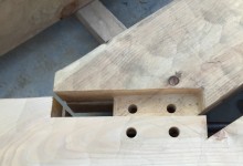
The 1722 East Derry Meetinghouse sports a parallel rafter chord king post truss. It has two pairs of ascending struts, and one pair of descending braces. The tie beam, or bottom chord is cambered, or curved, so that the center of the tie is an inch higher than the eaves. The tie beam is 44′ 6″ long and has mortises to accept four rafters, two struts, two braces, and a king post. Achieving 7 tight joints over a very shallow curve is challenging. Instead of calculating and trimming the end cuts of the rafters, struts, braces and post, the crew accommodated the curve by varying the depths of the housing. In the event of loose joinery, slightly shaving housing across the long-grain is much easier than shaving end-grain. The rafters were so thick that the depth of their housing increased 1/8″ from the rafter toe to rafter heel. The housing for the king post was exactly 1″ deeper than the housing for the upper rafters. Essentially, the crew adjusted housing depths to create an “ideal” straight tie beam out of a cambered bottom chord.
Jesse cutting housing with router and custom base
The crew cut all this housing using a router with a custom aluminum router base. The base is 2′ long, with handles, which gives the operator plenty of bearing on the timber. The finished frame fit together beautifully, with minimal futzing. We’ll continue to scribe rule our historic frames, but hope for more opportunities to square rule our new frames and near-reproductions.