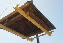
Hey, real quick! We’ve been cutting scarf fixes for enormous post feet, and fitting teleport pads for octagonal lanterns. Updates on Chestnut St Lantern, Brasen Hill Barn, and Jennison Barn, below.
Teleport Pad, Photo by Jacob Imlay
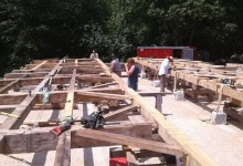
Chestnut St Church Lantern, Camden, ME: This cute little lantern was cut and fit at the shop, and is ready for transport to the Lyman-Morse boat shop later this week. There it will be fit with a 50-foot fiberglass spire and four 7-foot half-round hoods. Jake laid out the frame and Tim, Zach and Charlie cut and fit the joinery. Zach’s experience building guitars and Tim’s experience making furniture helped maintain tight tolerances. The entire lantern and spire will be laid down on a low-riding flatbed for final transport to the church, where a crane will tip the entire assembly up vertical. It is important that the joinery is tight in order to withstand the torque and lateral loads. Scott, Tim and Arron worked with Taylor-made builders up in Camden to plumb the tower and repair the belfry post feet at the Chestnut St Church. More about removing the old spire, here.
Lady Lantern, photo by Jacob Imlay
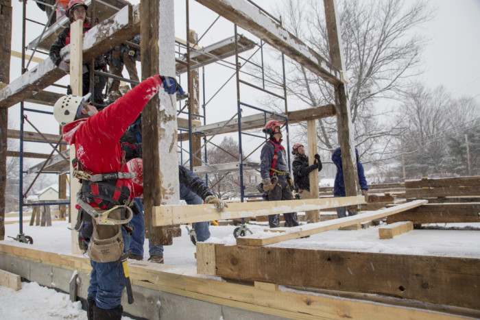
Brasen Hill Barn, Barrington, NH: Led by Dave and Dan, the rest of the crew have been busy with an enormous barn restoration at Brazen Hill Farm. The barn is beautifully hewn, with drive posts like tree trunks. The deterioration was extensive and the barn was completely dismantled for repairs. The extent of rot meant that the barn was heavily braced and was disassembled piece by piece by a crew of eight over two days.
Brasen Barn from above, photo by Josh McNally
Dave, Dan, Tom, Byam and Michael have been busy making traditional timber frame repairs at our shop in Nottingham, NH. Given the extent of damage, the crew worked hard to preserve any viable original material. That means a lot of dutchman and post feet fixes. Dan Boyle documented the repair and fitting process. A few of his process photos, below.
Undersquinted face fix, photo by Dan Boyle
An under-squinted dutchman repair can be used to repair the cheek of a mortise where a pin has blown out the relish. The rest of the post was in good condition and of a dimension and quality that is difficult (but not impossible) to find today.
Get (in the) Bent Brian, photo by Dan Boyle
After the rotten timbers are repaired or reproduced, we use come-alongs to pull the joinery tight and the bent square. Then we drill holes for the 1-inch oak pins that will hold the joinery together.
Eave fitting, photo by Dan Boyle
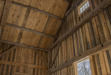
The barn is big, almost 70-feet long and 40-feet wide. It contains seven bents. The finished frame was raised almost a month ago, and Dave and Scott documented the process by helmet-cam. Stay tuned for the movie.
Jennison Barn, photo by Josh McNally
Jennison Barn, Lee, NH: New Hampshire Preservation Alliance has featured the Jennison Barn as one of their 52 barns in 52 weeks. The NHPA article captures why preservation is important on a human scale, from families to communities. Read their story, here.
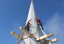
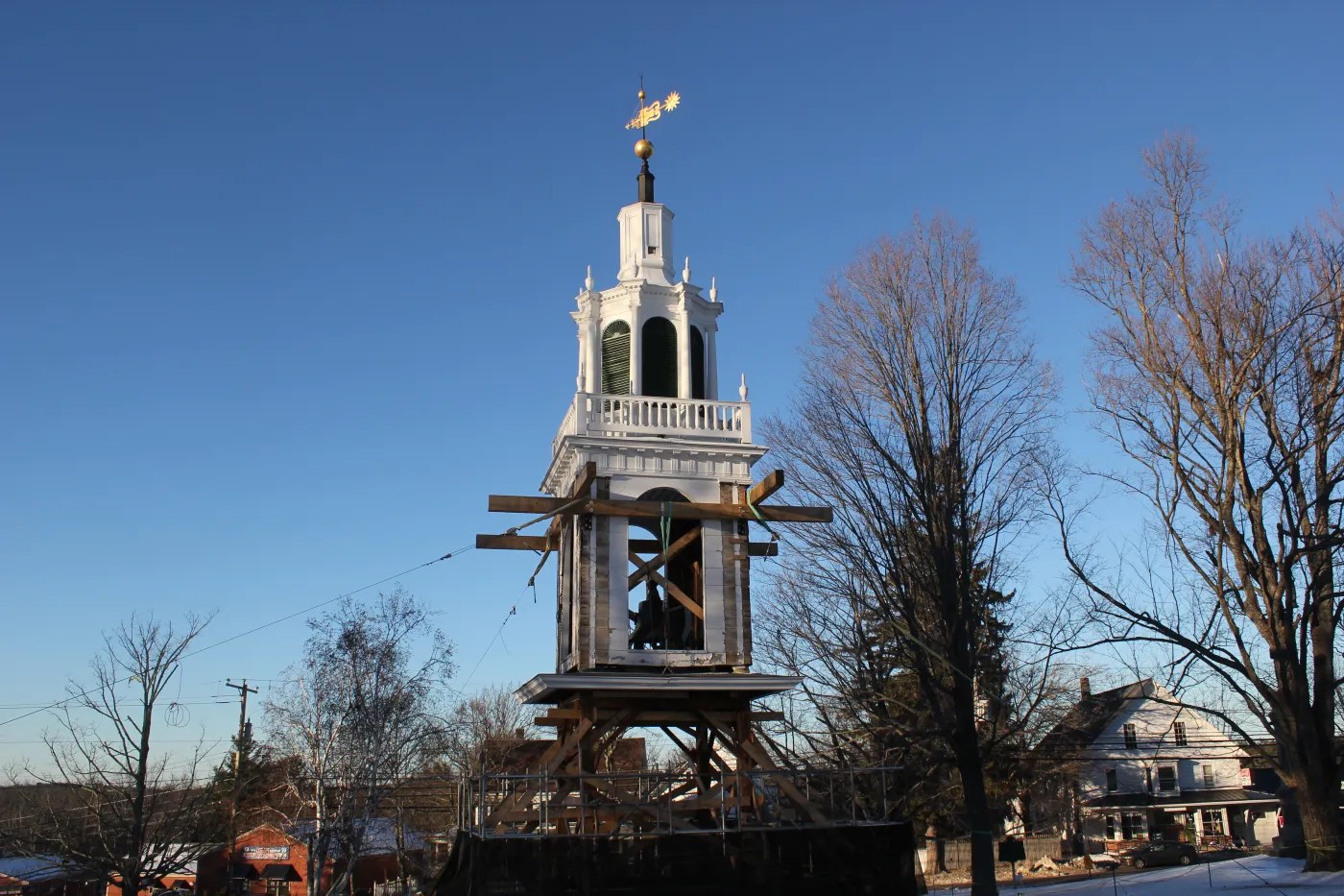
Last Thursday, I popped out of bed at 4 am, like Sal on her way to Bucks Harbor. Scott informed me that if I wanted to help remove the Chestnut St Church spire in Camden, I needed to be there by 6:00. By the time I arrived, Scott and Arron had set the rigging. About a third of the way up the spire, eight laminated KD 2x10s poked through the spire like an avocado pit ready to sprout. PTF was hired to direct the spire removal and design a timber-framed transition from the old belfry frame to the new fiberglass spire. We’d worked with the G.C. before on True-Randall farm, Taylor-made Builders are good folks who do high-quality work; so even though fiberglass replacements are not our thing, we got over ourselves because Taylor and his crew are such a pleasure.
This steeple is so tall that a 120′ man-lift couldn’t reach the weathervane on the day we went up there to remove the weathervane (oops). The main church is two full-height stories. Starting just below the main ridge-line, the belfry posts rise 30′ to a plate level just below the clock dials. The original spire rafters penetrate into the belfry, landing on a girt 5′ below the plates. The spire rafters pass through the dial level, behind four 6′ diameter glass dials. Above the dials, the original spire rafters were severed and sistered with relatively light, laminated 2x4s. That repair was performed in the 1990s by a talented and eager Eagle Scout. This go-round, we designed a timber-framed “lantern” that crosses the belfry plates like a crab. Eight 8×8 posts rest upon the lower crab and support a maintenance floor behind the clock faces. The upper lantern plates, or upper crab, extends well into the fiberglass spire, 6′ above the horizon of the clock faces. Four new fiberglass dial hoods will protect the dials, and be structurally fused to the new fiberglass spire. The lantern frame we’re cutting reproduces the telescoped framing levels found in this building and other historic steeples.
Lantern Iso, X-Ray
The model we’d created for the lantern design allowed us to accurately calculate the height at which the rigging would need to be placed in order for the spire to be slightly bottom-heavy as it flew. In fact, once prone in the driveway, the spire balanced like a seesaw on the fulcrum of its rigging. A top-heavy spire might flip mid-air, which would be just as dangerous and scary as it sounds.
Chestnut St Church, Crane, and Rigging
We hung a cage from the main ball of the frame to protect the weathervane from the rigging straps. We linked together the crane operators’ longest cables and our longest rigging straps, to connect the four corners of the metal frame to our rigging beams. The last strap was doubled over, resulting in an eight point pick.
Spire cage
The crane flew the rigging up to the crew on the top of the staging, and we pulled the rigging straps away from the spire as the operator located the ball directly over the weathervane. The rigging was accessed by ladders off the staging, which was less efficient than it was photogenic.
Teamwork
Once the rigging was securely attached, we crawled inside the spire and used saw-zalls to cut first the spire sheathing, then the mast and then all eight rafters. In my experience, the penultimate step of severing the last connections is the most stressful and variable part of the entire crane day. As Arron warned the crew, a forgotten toe nail could prevent the spire from releasing safely and evenly. We were lucky to have a skillful crane operator from Keeley. We wanted the crane to take enough weight, and put enough tension on the rigging to prevent our sawzall blades from binding, but we did not want the spire to bounce or release with any energy.
Witch’s hat with a crown of thorns
Scott and Arron checked in with the operators. When we started cutting the sheathing, the crane had 1500 lbs of weight on the ball. For the mast, 2500 lbs. As the last of the rafters were cut, the crane was taking 3500 lbs. Unfortunately for the spectators on the ground, a safe spire removal looks slow and boring. Unfortunately for my story, the spire released without any hitches. The spire weighed about 8800lbs, which reflects its light framing.
A Bittersweet Triumph
The crane operator lowered the spire safely to the street, and the crew cut the cone into sections small enough to carted away by a pulp truck. The Penobscot Bay Pilot got some beautifully boring drone footage of the removal, and covered the story, here. For more photos of our process, visit our Flickr album.
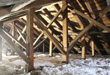
In 30 years of investigating New England’s historic churches, PTF has never encountered a better truss system than that of Eastport’s Central Congregational Church. Built in 1828, the roof system combines the traditional strength of a king post-prince post truss and principal rafter-principal purlin roof with innovative tying geometry that prevents the pitfalls of rafter slippage experienced by other churches we have investigated. The roof geometry has maintained its joinery even though the foundation appears to have suffered a landslide into the basement of the church, and most of the carrying timbers are being carried by their floorboards.
Front Facade
The exterior façade stands out for the near complete preservation of its original composition and trim detailing. It serves as a prime example of how some Federal Era builders used relatively simple building methods and a small collection of hand tools to create arresting architecture by integrating detailing with overall composition of fenestration and major trim elements. The proportions of the pilasters are arresting, but the trim is not ornate. The pilasters are not fluted and the capitals have a simple, muted profile, devoid of carvings. The capitals are incorporated into the architrave and terminate at the full length gable return, which is deep, but has a short fascia. The pilasters terminate neither in an efflorescence like late Federal, nor in a broad stripe like Greek Revival. Instead, the return is a fine line. An eyebrow window, the width of the center third, punctuates the tympanum. The sash is decorated with three ovals drawn in tracery that repeat the rhythm established below. The building presents a façade that is both austere and elaborate. Austere in that the building is embellished exactly to the degree necessary to show reverence for the building’s purpose, and no more. Elaborate in that the design reflects a serious consideration for proportion and how every detail relates to the whole.
Cantilevered carrying timber
The failure of the foundation can be seen from the outside of the building. In many places, the grade almost reaches the bottom course of clapboards. In the rear northwest corner the foundation stones have caved in. A river runs through the right north bays of basement, where the clearance is 6’. The grade slopes upward to the south; the clearance in the southern joist bays is 1’ – 2’. Bulk moisture and lack of ventilation have deteriorated the timbers over time and the carrying beams bear the scars of inadequate repairs and forced-air heating ducts. The two rearmost carrying timbers are no longer connected to the sills, and the third is fractured. A replacement sill, under the narthex, is undersized, so that the adjacent joists don’t quite reach it. Fortunately, most of the joists are so oversized that they will function ably after the exterior ½” of slough is removed with a drawknife.
Sweet daisy wheel
In the process of undercarriage replacement, much of the foundation will also need to be rebuilt, and as much of the grade removed as possible to reveal pier footers and ensure good drainage and improved ventilation. Foundation and grading will comprise the bulk of repairs.
King post – prince post truss system, looking rearward
The roof system has withstood the extreme deterioration of the foundation and undercarriage due to its exceptional design and level of craft. To the layperson, the Central Congo truss system is beautiful; the hewn surfaces of the timbers are shiny from the use of a sharp adze, and gently mottled, like hammered copper. At the center of the truss, the broad diamond-shaped head of the king post hangs from the apex of the rafters. Its long slender neck widens at two sloping shoulders from which two struts spring. Two wedged braces form an “X” connecting the trusses along the longitudinal axis. The struts each land in a undersquinted notch at the head of a prince post, from whose knees spring yet another pair of struts. There are two additional struts, or jack posts, just outside of the prince struts.
King post – tie connection with stirrup strap and butterfly bolts
To the timber framing professional, the roof system is sublime. The truss itself is at the peak of craft, from the detailed shaping of the king post to the undersquinted joinery at the prince posts. The bottom chord, or tie beam, 10” x 11”, appears to have forced camber so that its center is 2” higher than its ends. The king post/bottom chord joinery is reinforced with an iron stirrup, fastened with butterfly bolts. Not only is the truss exceptional, but they are tightly spaced, less than 10’ 6” on center. But it is the framing between the trusses that is truly innovative. The roof system is a principal rafter, principal purlin roof, with common rafters between the trusses. The principal rafter, or upper chord, is 9” wide, and tapers from 9” deep at its apex to 11” deep at its foot. It is connected to the next truss by a horizontal beam, called a principal purlin. The purlin is parallel with the eave, and about halfway down the roof pitch. Between the trusses, there are three common rafters. In a typical church roof, these commons land on a flying purlin that is joined into the ends of the adjacent tie beams. The problem with this design is that the tie beam is already missing a good chunk of material from the rafter mortise, and the rafter is actively pushing outward against the relish on the end of the tie. The flying purlin is often too undersized to really resist the thrust of the common rafters, and bows out and blows out the end of the tie beam, further compromising its joinery. Commonly, this results in the upper chord of the truss slipping out past the end of the tie.
Truss Iso
In the Central Congregational roof, there is no flying purlin. Instead, each common rafter lands on its own short tie beam, perpendicular to the eave, which runs over the top of the plate and ties back to a ceiling purlin connecting the trusses. The ceiling purlin is 9’ from the end of the tie so it doesn’t compromise the rafter joinery. The ceiling purlin and short tie are substantial. They are strong enough to actually resist the outward thrust of the common rafters. This means that the rafter mortise in the end of the tie is resisting a lot less thrust, and not a single one is blown out or even slipping. Additionally, the principal rafters are fastened to the bottom chord with an iron trunnel pin. The short tie solution is also found in the North Free Will Baptist Church, just up the road, and appears to be unique to Eastport. The truss system appears to be free of rot or any other damage.
20th century spire rafter-belfry post connection
The tower was significantly rebuilt in the late 20th century, and while the repairs were not in-kind, they appear to be functioning. With the exception of one girt stabilization, all the tower needs is a good reaming and a coat of paint.
The octagonal belfry and spire have clearly been through multiple generations of repair. The original spire was blown off the building in the Saxby Gale of 1869. This apparently does not include the belfry, much of which was also rebuilt in 1986 and 1994. Above the tower plates, the eight spire rafters join directly to their posts about 5′ from the belfry floor. There is no intermediate horizontal girt level for them to land on; the spire rafters join the tower posts at the center height of the louver openings. At the louver header, each spire rafter is further secured to a tower post by a 1 ½” iron stirrup that wraps around the rafter and is bolted to either side of the post. The belfry plates do not cross over the tops of the plates, they intersect the plate 6” below the top of the post. The tower posts terminate in a level cut. A belfry roof rafter connects the top of each post with a spire rafter.
King and prince post truss, looking frontward
Access to the building has improved significantly since our first visit in summer of 2015. The removal of substantial pigeon detritus and installation of lighting is a testament to the high-quality stewardship of the Tides Institute and Museum of Art. The organization stands out for its initiative, community involvement, and generation of momentum. TIMA is clearly committed to the continued preservation of its historic structures.
This blog post is a severely abridged version of the Central Congregational Church assessment that we performed for the Tides Institute this spring. TIMA has published a lot more about the building’s history, here.
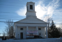
Deep into the winter of 2014, a banner stretched like caution tape across the front of Northwood Congregational Church. It implored commuters from Portsmouth and Concord, “Don’t Judge a Church By It’s Outside. Look for Restoration Coming Soon!” The red text on white vinyl was the freshest trim on the front facade. The porch sagged, the paint was peeling, and the carved finials once crowning the belfry were many years gone. Still, any driver might have noticed the huge fluted columns more than 30″ in diameter. An unhurried driver might have recognized the church as one of the best examples of Greek Revival architecture in the state, even in its dilapidated state. The slight skew to the banner underscored the meaning in its message. No passerby could have guessed the depth of commitment within the building committee and dynamism of the congregation behind it. The PTF crew restored their church from 2015-2016.
The work was far-ranging, from repairing lightning damage in a king post to reproducing those finials from photographs. But the most impressive repairs were in the columns. The open portico is an important structural element, bringing half of the belfry weight to ground. But they are also an important decorative element, each stave carved with a tapered flute. When we first assessed the site, in winter of 2014, the deck supporting the columns sloped dramatically away from the building. The bottoms of the columns themselves were rotting, showing signs of decay, and the belfry leaned precipitously toward the road. Beneath the deck, we found a rubble stone foundation build on grade. There was no footer, no stone below grade, much less frost line. We supported the belfry on timber deadmen, staging, and steel I-beams while we removed the columns, replaced the foundation, rebuilt the deck, and repaired the columns. Arron documented the process in a series of photos, below.
He described the tilt of the porch as “not quite 45 degrees.”
The crew transferred the belfry weight to structural staging, timber “deadmen”, and a steel I-Beams that picked up the corners diagonally. The rigging was accessed and adjusted by the crew using ringlock staging. Once confident that the belfry was adequately supported, the crew began to cut away the old, decaying deck, to prepare the columns for removal.
Using a chain fall, Tom lowered the columns safely to the ground. A custom carriage was used to transport the columns to our shop. At nearly 20′ long, one column claimed the entire trailer.
After the columns had been removed, we focused on foundation repair. The parish hall foundation had a granite cap stone foundation that was built at grade; there was no frost wall or footers beneath it. The parish hall was supported on cribbing and jacks, and the granite capstones were carefully removed. Using extreme care, Bob Cantwell excavated the soils below the parish hall. Chris McKinnon poured substantial footers. Then he used a one sided form to pour a frost wall up to and underneath the parish hall slab. The granite capstones were replaced, and new sills installed.
The front wall of the church, under the columns, was similarly unsupported. The sagging deck was removed, and new footers, frost piers and frost wall were formed and poured. This foundation accepts the all of the weight from the front pediment, the portico, and half the tower loads. The crew replaced the deck framing with white oak. The dimensions and layout of the timbers were identical to the original. They were tenoned into mortises on the front sill, and pitched slightly away from the building.
The new deck will support the portico and tower above. The structural columns were hollow. They were constructed out of individual staves toe-nailed to a series of round wooden forms. We assessed each individual stave for damage, trying to retain as much original material as possible. Where replacement was necessary, we cut tapered Eastern White Pine dutchmen and spliced them to the original flutes. Each column capital was inspected, repaired and painted. They were constructed from rings of boards stacked, rotated, and laminated together. Each top was modified slightly to accept a structural post. Structural timber posts were hidden inside the fluted columns. The posts were a necessary upgrade that will better transfer tower loads to the ground. The structural post was installed directly beneath the front exterior tie beam. The columns were not originally centered under the beam, and are not centered around the structural post. Once the front half of the columns is installed, the structural post is completely hidden. The front portico looks as it did originally, but is much more structurally sound. Once the columns were replaced, the crew could focus on structural repairs inside the belfry. The lower tower girts were replaced in-kind, along with the belfry bed timbers. All framing repairs were completed without dismantling the tower or removing the belfry. Once the structural repairs were completed, the exterior trim was restored. Balustrade elements were carved by hand, matching the few remnants of the original details, and early photographs. New louvers replaced poor reproductions. Bump outs were flashed with copper and new copper step flashing was installed at the base of the tower. The copper belfry roof was in good condition, and was modified slightly to accept the balustrade. George McKie, of Service Painting out of Lynn, MA, did a beautiful job of scraping, priming and finish painting. We are very proud of the result, but more than that, we are grateful to have been invited into this community. This project was so successful because the building committee recognized the importance of their landmark and committed themselves to appropriate preservation. They were one of the most responsive and knowledgeable groups with which we’ve ever had the pleasure to work.
We all have illusions about longevity. Many people think that a building’s strength is derived from its foundation, made of stone, or brick, or concrete, but that’s only partly true. A good foundation is a blessing, but a bad foundation is not damning. We’ve seen so many foundation failures that in a well-designed timber frame, we consider the foundation a sacrificial element.
The Lord Barn is one such example. Over the past decade, the barn had emulated a pat of butter on hot toast. Its fieldstone foundation was slipping, and the eave sills had rolled out from under the plates. The building looked dangerous to teenagers. With this kind of failure, we expected to find a lot of rot. But with the corrugated metal roof and deep overhangs, water infiltration was never the main problem. There was plenty of air flow, so bulk moisture wasn’t being trapped inside the building. While the foundation and undercarriage melted into the ground, the timbers above stolidly endured.
Lord Barn plate-to-post connection.
Dating a barn like this is hard, and not just because it’s a hot mess. Many of the larger beams, the tie beams, rafters, plates, and posts, are hewn, which means that their surface was smoothed with an adze or broadaxe, resulting in a texture like hammered copper. Hewing was replaced by up-and-down milling throughout the 19th century, depending upon proximity to a sawmill, and frugality. But the frame design and joinery of the Lord Barn follow later trends, especially the plate/post connection. The plates are discontinuous, and are joined into a mortise at the top of each post. The end of the plate rests on a 1″ let-in, or shoulder, characteristic of square-rule joinery, which became popular in the late 19th-century. Hewing is a labor-intensive and thoroughly handmade practice, while square-rule framing, although also cut by hand, was an innovation in efficiency that made pieces more uniform and interchangeable.
Lord Barn, principal rafter-principal purlin roof, with stacked common rafters.
Both gable ends have integrated pocket doors, where the door slides through the middle of a 12″ deep post. Pocket doors look slick, but aren’t suited to this climate; the door and post expand and contract, and the gable sill isn’t well-protected. Arron says Tom Visser’s field guide dates interior pocket doors between 1870-1880, but I can’t find the book to quote it directly, so.
Lord Barn, Rafter-Tie Beam joint
The roof system, with common rafters stacked over a principal rafter-principal purlin frame, is 1870s’ish. The common rafters are sawn and relatively small, 3″ x 5″. By stacking them over the purlins, the major roof framing is better protected. The rafters join the tie beam well inboard of the end of the tie, which means more material in the tie is resisting the outward thrust of the rafters. There is also better airflow around the principal rafters and purlins. In the Lord Barn, the common rafters run well past the plate, creating a deep overhang, which protected the sidewall framing as the sills slid and spread. The frame’s design brackets this barn between 1860-1880. We think it is a late example of a totally hewn frame.
Lord Barn overhang
When the foundation failed, the joinery was put into tension. In a pinned mortise and tenon joint, the pin prevents the joint from separating as the building settles and moves. But it doesn’t matter how strong the oak pin is once the relish past the pin hole gives way. In places where the joinery failed, tenon relish was the culprit.
Lord Barn, post-top tenon relish failure
The left eave sill rolled right off the foundation, pulling many of the left eave posts with it. It racked the entire frame, the posts pulling away from the loft girts. The tenon relish, just past the pinhole, was sheared in nearly every loft girt, and in many of the post tops, too. In bents where the post-tie beam connection held strong, the end of the tie beam dropped dramatically away from the rafter.
Lord Barn, rafter-tie beam separation
A year ago, we disassembled the barn with the entire crew. The clients, Pat and Paul Boisvert and Linda and Frank Underwood, de-nailed the timbers and helped dismantle the bents once they were on the ground.
Paul and Frank pull sheathing while Pat and Linda de-nail studs.
Over the course of the summer, the clients had the foundation poured and built the floor system themselves. In the Fall, PTF made the few necessary repairs to the frame which included small repairs to a few post feet, and some face fixes where the pin had checked the cheek of a post or tie beam.
Third H flying in, photo by Joshua McNally, jamcnally.com
Almost exactly a year later, the whole crew came together again with the clients to re-erect the frame. Because of the discontinuous plates, a frame like this needs a lot of hands on crane day. We assembled each bent into two “H’s” on either side of the drive, with an eave post, a drive post and a loft girt. There were five bents and ten “H’s”.
Arron signals the crane operator as he places the “H”. Photo by Joshua McNally, jamcnally.com
We started in the left side aisle. The crane lifted the left rearmost “H”, and the crew stabilized it with a KD kickstand. Then two loft girts were installed, perpendicular with the first “H” and propped up with temporary deadmen. The second “H” was stood up by the crane and we worked in two teams of three to engage the loft girts. Two additional people on rolling staging lifted the plate and inserted it between the two eave posts.
Engaging the fourth H with the plate. Photo Joshua McNally, jamcnally.com
When the first two “H’s” were plumb, all the joints were temporarily secured with KD gussets. At this point, the box was relatively stable, and we moved onto the third “H”. After the left side aisle was completed, we repeated the process in the right side aisle.
The crane operator flies a purlin to Dan. Photo by Joshua McNally, jamcnally.com
After a late lunch, the crane began flying in the upper triangles formed by the tie beam and rafters. The installation was complicated because the bottom of the tie beam needed to engage with four posts and four braces. Over time, a few of the tie beams had bent to conform to the drooping left eave, and each tie beam fit with some idiosyncrasy. Additionally, there was a pinned purlin between each pair of rafters. These beams needed to be installed by crew-members on staging at roof height. Before each tie triangle was flown, two staging towers needed to be dismantled and re-erected in the subsequent bay in order for us to be able to install those principal purlins. Every member of the crew and each of the clients were needed to erect the frame in a single crane day. It was a lot of fun.
Lord Barn Frame, Re-erected, Photo by Joshus McNally, jamcnally.com
Ultimately, the frame was saved, but the foundation was a lost cause. The relative flexibility of timbers and the strength of their joinery often allows them to outlast their granite and fieldstone foundations.
Crane Day crew, photo by Joshua McNally, jamcnally.com
Our newest crew member, Joshua McNally, took a bunch more lovely photos of our crane day and of the Lord Barn after the roof was sheathed. For more, photos, explore our Flickr album.
I write a lot about our unusual jobs: a deserted island, an elevated dance floor, or a building-sized jewelry box, but most of us got into this to do jobs like the Jennison barn. The job incorporates so many of PTF’s defining motifs: barn preservation, adaptive re-use, local history and creative clients. The Jennisons called in early 2015 about a barn that had collapsed under extreme snow loads. After assessing the damage to the frame, and a long period of negotiation with the insurance company, we concluded that the barn was not salvageable, and that its replacement would need to be significantly scaled down. Ultimately, too many of the posts had snapped in the collapse, and the replacement coverage did not include the embodied value of the craftmanship and timber joinery. Fortunately, PTF had dismantled a smaller frame the previous year, and had hoped we could find it a home nearby.
Brock standing
Brock’s Barn was located at Brock’s Crossing in South Berwick, near Slut’s Corner (the etymology of “slut” is facinating!). Simeon Brock bought the farm in 1790 and lived there with his wife, Judith, and their five children until his death in 1814. None of the children married or moved from the property. The youngest, Deborah, began working for the Portsmouth Manufacturing Company when she was 23. She was known for walking the mile and a half commute to the textile mill and for her thrift. Deborah managed the farm until she died in 1883 at the age of 74.*
Two barns in one, 18′ x 18′ extension on the left, 28′ x 42′ on the right
The Brock barn was actually two barns in one. A smaller, earlier 18′ x 18′ frame was expanded with a 28′ x 42′ frame. The rafters and ties of the former were extended to match the dimensions of the latter. Above, you can see the two adjacent posts where the gable ends of the frames meet. The 18′ x 18′ frame appears to have been built earlier, as the joinery was clearly retrofitted to expand the footprint and raise the peak to match the larger frame.
18 x 18 barn, original roof framing lower right. The ridge was raised, and roof plane extended.
Both frames have hewn timbers and scribed joints. Both frames exhibit the English tying joint, where the plate crosses over the post, parallel with the eave, and the tie beam crosses over the top of the plate. The interior face of the post, about half its thickness, extends past the plate to join to the tie beam with a teasel tenon. Both frames are eave entry, which was an earlier, “English”, floor plan. Both frames are early enough that it is difficult to date them definitively. The larger frame has up and down sawn braces, some of which exhibit the natural curvature of the limb, as above, but this does not date it. The first saw mill to operate on the neighboring falls was established in 1634. The 28′ x 42′ frame is also distinguished by much larger timbers, especially the lower tying girt and longer braces. Based on framing methods alone, it could have been constructed anywhere between 1790 – 1840.
English tying joint joins post top to plate and tie beam
Given the history of the property and surrounding town, we suspect that the 18′ x 18′ barn was built at the time Simeon bought the property in 1790. The smaller frame may have preceded the Brocks, but the only evidence is that they so drastically altered it. The 28′ x 42′ frame may have been built towards the end of Simeon’s life and appended to the smaller frame without any retrofit. The craftsmanship of the alterations to the 18′ x 18′ is significantly later and of lower quality than either barn frame. Some time after Simeon’s death, one of his children or one of Deborah’s farm hands may have extended the barn across the gable, and raised the ridge height. These are the histories we write as we repair the frame, fine-tuning each tenon and scarf joint.
Post scarfs on parade, photo by Dave Ewing
The Jennisons bought the 28′ x 42′ frame. Dave, Tom and Dan performed the frame repairs, and the results are stunning. Standing, the barn is defined by its array of post repairs. Each scarf joint was designed to maximize the preservation of original wood, and withstand the array of forces endured by each post. They planed the new timbers and fared their edges to blend seamlessly with the old.
Bent assembly, photo by Dave Ewing
Dave enjoyed the opportunity to work consistently on timber frame repairs. Nearly the entire roof system was in good shape, and he said, “getting to preserve that was a joy.” He also thinks that part of the reason the rebuilt barn looks so good is that all the new timber ended up in the same quadrant of the barn, in the new loft. The crew repaired the barn in our shop in Nottingham, NH and fit the bents together inside the shop. Then they disassembled the frame and transported it to its new home in Lee. Nearly the whole crew attended the raising, and both Seths and Brian assisted with the finish.
Jennison Barn, rebuilt. Photo by Josh McNally
Charlie Jennison plays saxophone and teaches music at Exeter Academy and UNH. He wants to the barn to serve as a concert space, and we hear that they’re already hosting successful events. Along with the outdoor sculpture gallery across the street, the Jennisons are creating an art enclave in Lee, and we’re proud that the barn gets to be a part of that.
The following photos of the finished Jennison Barn are by Josh McNally. Visit our Flickr page to see photos of the two frames before they were dismantled. Brock’s 18′ x 18′ frame is dismantled and looking for a good home.
Sub net pier from the top of the Wood Island staging
This blog goes dark when it’s sunniest. Seems like every day this summer has been a good day to be working outside. We’re installing the last repairs to the undercarriage at East Derry First Parish Church, installing electricity for the clock at Hampton Town Clock Tower, waiting for the last of the ceiling to be removed at the Winter St Church in Bath and finally hanging exterior trim at Wood Island. They’re all big jobs, with little updates.
East Derry First Parish Church and steeple
The First Parish Church is the biggest, heaviest building that we’ve ever lifted (thanks to Rick Geddes of Geddes Building Movers). The building was estimated at 188 tons, but actually weighs 288 tons. For the first time in PTF history, we bent a lifting bracket, as well as the shaft on a hydraulic jack (which is why we always use redundant rigging, and shim hard to ground). “It’s been quite a challenge,” says job lead Brian Cox. A poorly conceived connecting ell was dumping water and moisture onto the historic meetinghouse, resulting in a nearly complete undercarriage replacement. Almost a year ago, we removed the steeple from the building and placed it on the front lawn to await repairs. In the early spring, the building was lifted, a new 4’ basement was excavated and concrete foundation poured. In May, the church was lowered onto its new foundation. Throughout the summer, Brian Cox, Dan Boyle, Seth Richard and Kirk Hennequin have been working diligently to replace any rotten girts and floor joists. Paul Lindemann on the restoration committee has kept a thorough blog to document their process and progress, and the building’s history. Read more here.
Hampton Town Clock Tower
The small Northern contingent of Lee, Jake, Scott, Seth and Jess built the Hampton Town Clock Tower this Spring and Summer. The standalone clock tower is building-sized display case for Hampton’s historic Howard round top tower clock. The 8-day clock, with dials that read “M E M O R I A L G I F T” instead of numerals, was given to the town in 1897 and ticking in the Odd Fellows Block until the building was destroyed by fire in 1990. The building is a design departure for PTF, as it references the Odd Fellows Tower, but does not replicate it. The four gable roof, topped with a “witch’s hat” spire, and four corner pent roofs was taken from the original building. Below, the body of the building is much simpler than the Odd Fellows tower. The 10’ arched windows reference the original arches, but the elaborate corner trim was eliminated, allowing the historic clockworks to take center stage. The clock will stand on a low lofted floor above the bell, making the clockworks accessible to its civic owners for the first time in history. Phil D’Avanza is completing repairs on the clock, and Skip Heal, of Northeast lantern, donated an enormous reproduction of the original weathervane. Read more about history of this clock, from installation, through destruction, disappearance and ultimate restoration.
Sagadahoc elevated timber deck, partially erected
In August 2015, high winds shook loose nearly a third of the coved ceiling at the Winter Street Center in Bath, ME. Enormous swaths of plaster and lath crashed onto the pews, and hung loosely from the trusses. Remediating and repairing the 26’ high ceilings posed a unique challenge. The sanctuary needed to be cleaned of hazardous debris, and the rest of the dangling plaster needed to be removed. Following the removal, Sagadahoc Preservation will need to raise the funds to make necessary truss repairs and ultimately reinstall the ceiling. The process is expected to take years, and a lot of staging. Given the original timber framed floor framing, with large, widely spaced girts and joists, and the time-span of the project, it made more sense to build a timber-framed deck 13’ above the floor, and cantilevered over the balcony. The deck is perfectly flat, and allows EnviroVantage to safely remove the ceiling where it is 6’ above the deck at the eaves, and from rolling baker’s staging at the center of the room. The timber deck even allows Sagadahoc to continue to use and show the sanctuary as they fundraise for the next phase. Jake Imlay wrote a great post describing the building and our approach there. Coming soon.
Wood Island Life Saving Station boathouse and tower
The restoration of the Wood Island Life Saving Station, in Kittery Harbor, has had Arron and his salty crew of Tom, Dave, Jake, Tim, Scott, Jess, Gail and Kendall up to their armpits in work. The life saving station was built in 1908 for the U.S. life saving service and became part of the coast guard in 1915. The U.S. Navy used the site to defend Portsmouth Naval Shipyard against U-Boats during World War II. Since the early 1950’s, the life saving station has been unused. Although the island is a popular destination for kayakers launching at Fort Foster, the building fell into dangerous disrepair, with radiators dropping through the floors. The Wood Island Life Saving Station Association applied for National Register status based on the building’s historic significance, and the integrity of the original interior trim and cabinetry. Over the summer, the intrepid crew rebuilt the boathouse, porches and dormers. As ever, sheathing repairs revealed more extensive rot than expected, but we’re finally finished with taking things away, and can focus on rebuilding. This week, we commenced with hanging reproduction trim milled right in our shop in Berwick. I’ve worked in wind like that on one other job-site: Mount Washington. We hope to have the building roofed by the end of September, which will mark the completion of phase one. And we’ve had some good press, from the Portland Press Herald to the Associated Press. Read more here.
As much as we’ve enjoyed these projects, we’re looking forward to Fall, continuing repairs at the Abyssinian Meetinghouse and Troy Union Church and commencing work at the New Harbor Methodist Church, among others. When it rains, check back for more.
The Troy Union Meetinghouse had a crane day last week. The long-leaning steeple was partially dismantled, leaving behind the two front posts to stand like wooden antennae. The entire replacement frame has been cut by a crew of local craftsmen, and will be resurrected before the end of the summer. Read more about the process here, and show your support. If you don’t see a video below, click on the link to watch the story.
The First Parish Meetinghouse of East Derry, NH is preparing for a big anniversary, its tricentennial. What does one even get for a church on its 300th? Wood? Copper? Both, as it turns out. Beginning with a thorough assessment and rehabilitation plan in 2011, the congregation has been working steadily to repair extensive damage throughout the steeple and undercarriage. This past fall, we extracted the belfry and lanterns from the steeple stack. After the new year, we documented the upper sections from a woman-lift and dismantled them from finish to frame.
Lower lantern roof, crowned with urns
As we surgically removed trim, we encountered earlier salvage efforts. Dan and Rod peeled back the gracefully curved roof between the upper and lower lanterns and revealed an oiled sailcloth roofing. The sheathing below was labeled November 1916.
Lower Lantern Posts
The frame was in far worse shape than we expected. Years of roof leaks and patchy repairs had finally overtaken the stout timbers. Once the lower lantern posts were exposed, we wondered how the structure was still standing and realized too late the bravery of dismantling it. Above, you can see that the six of the eight posts were hollow or non-existent at the top. An extensive repair campaign in the 1990s consisted of bolting channel steel and L-brackets to the crossing crab members (a “crab” is a horizontal web of timbers that spans the posts of a lower level and support inboard posts above). Looking at this picture, stiffening the crab fell far from the root of the problem.
Lower lantern crab above belfry ceiling
The crew struggled to free the timbers from their steel cages only to discover a corpse. It’s tragic that this rot wasn’t addressed when the church raised money for its repair two decades ago. A comprehensive, traditional approach at that time would have prevented the wholesale replacement necessary today.
Truss spread
In 1719, Scotch-Irish immigrants, fleeing religious persecution in Northern Ireland, settled the area that became East Derry. In 1722, they built their first meetinghouse on this site. The present structure was built in 1769. By its centennial, in 1822, the congregation had so grown that they cleaved the building in two and dragged one end 24 feet to the east. Above, you can see the first additional bay, indicated by the absent strainer beam and braces.
East Derry Wall D
In our assessment drawing above, the strainers and bracing between the trussses in bents 3 and 4 and bents 5 and 6 are non-typical. The strainers and bracing in bright green are non-existent; that is the bay in the photograph above. The yellow strainers and bracing between bents 5 and 6 do not quite reach bent 5, they are connected by a series of sisters and scabs. The evidence in the frame complies with the history: our hypothesis is that in 1822 the building was split between bents 3 and 6, (originally bents 3 and 4). Bents 6 through 9 were dragged to their current position, and bents 4 and 5 were built as exact reproductions of the originals. The strainer and braces that used to connect bent 6 (originally 4) to bent 3 were sistered to bent 5, and the strainer between bents 3 and 4 was deemed unnecessary. We are curious to uncover more of the eave wall framing, specifically the plates and the sill scarfs, to see whether there is more evidence to support our theory.
Parallel rafter chord truss
The East Derry First Parish truss is iconic. It has a king post in the center, with parallel rafter-chords and crossing pairs of ascending and descending struts. The king post is in tension, picking up the tie beam at the middle of its span, and the ascending struts rise from the king post and prevent the rafter from sagging. In the Timber Framing series, “Historic American Roof Trusses,” Jan Lewandowski explains:
Outward pressure on the walls can be eliminated entirely by affixing the feet of each rafter couple to their own tie beam. The problem of sag can then be addressed by hanging a joggled vertical member, or kingpost, from these rafters and using it in tension to support the midspan of the tie beam… By a less obvious intuitive leap, it might be realized that the midspan of the long rafters can be kept from bending by struts rising from lower joggles on the suspended kingpost.
East Derry Bents 1-4
The parallel rafter-chord is an innovation that protects the Achille’s heel of the king post truss. The casual observer often assumes that the joint between tie and king post is where we would most frequently see failure over time. I’ve seen many iron stirrups that attest to the builder’s concern for this joint. But most trusses fail at the rafter heel, where the upper rafter-chord intersects the tie beam. Of this foot joint, Lewandowski writes:
Those we can inspect seem more prone to failure and impairment than most other connections in the truss, for a combination of reasons: the lack of relish beyond the mortise and the large forces involved, coupled with the low angle of attack of rafter to tie, all exacerbated by a high incidence of leaky eaves. The significance of the roof slope is that the geometry of low-pitch roofs channels more horizontal force against potential long-grain shear failure in the tie at the foot joint than it does comparable vertical breakout load on the kingpost at the peak (see TF 72, 19). The point: on both empirical and theoretical grounds, the principal rafter-to-tie beam joint is the likely weak sister in the mix.
In Sedgwick, we saw the foot of the upper chord shear a 2″ x 12″ x 22″ block clear off the end of the tie beam (It was about the size of a hefty wedding-present-breadboard). With a parallel rafter-chord truss, the duties of principal rafter and upper chord are separated. The principal rafter, the top angled timber, carries the roof, while the upper chord, the inner angled timber, carries the compressive loads created by the truss. The upper chord intersects the tie beam farther from the end of the beam, thereby protecting the relish just past the joint from shear. We so liked this truss that we reproduced it in a building where it will be on grand display: the Lewis Conservation Center.
Steeple extracted
Paul Lindemann, East Derry historian and devoted parishioner, keeps a detailed website documenting the history of the church and their repair process. The Nutfield History blog is a fascinating read for anyone interested in New Hampshire history or building history in general. The blog also benefits from Lindemann’s web design skills, something that doesn’t always attend the dual callings of historian and parishioner.
The vigor and ingenuity of the immigrants who built this Meetinghouse is evident in its frame. We honor their labor with our efforts to preserve it. In 300 years, what will historians write about the immigrants seeking refuge in the United States today?
The client’s wedding was in a week, and the barn in which he’d marry was in pieces on the ground. It was crane day, and a Friday, two things that don’t usually go together. In the worst case, a crane day on Friday means you don’t have an additional weekday in case you hit a bad snag; in the best case, it means the crane operator wants to get home, and the roof frame flies in fast and loose. In a week we’d complete a job started almost exactly four years earlier. Back then, Arron was patrolling the net, looking for a barn in need of saving, and spotted a damsel in West Poland, ME. That Saturday, he dragged his teen-aged son with him to visit the barn and get some driving practice. The frame was for sale, but not the land beneath it. It would need to be documented, disassembled, repaired and rebuilt elsewhere. When Arron arrived, another potential buyer was already poking around.
Before (September 2011)
Arron wanted to repair the barn, but needed a buyer; Charley wanted the barn, but needed someone to repair it. It was a good match. Since then, PTF has embarked upon a number of projects with Charley, most notably the disassembly, repair and rebuild of his Carpenter’s Shop two winters ago. The West Poland barn was neatly stacked in a Dairy barn at his home, awaiting its turn on a long to-do list. This fall, as Arron’s son prepared for his sophomore year in college, PTF erected a barn that had spent four years being designed and refined in Charley’s head.
Barn Frame Iso with transparent grade
Charley needs the barn to house his three draft horses, donkey and a flock of sheep. The draft horses wouldn’t fit under the barn’s original girts, 6′ 4″ above the sills, about 6 inches shorter than your standard doorway. He designed a foundation that raised the posts 2′ 8″ above grade, creating 9′ of clearance for the horses. The perimeter posts are each tenoned into a sill, which rests on a foundation wall. Each drive post lands directly on a 8″ x 8″ granite pier. Precisely 7′ tall, the piers rest directly on two longitudinal footers, 4′ below grade. A frost wall was poured between the posts; it’s top level with grade. Each post is point loaded upon a foundation wall that extends below the frost line and rests on a connected footer. This will prevent the posts from moving due to annual freeze and thaw. Ensuring that each drive post landed on its granite post required precise cutting, measuring and measuring again.
The barn we took down was built in the mid-19th century; it has hewn posts and both sawn and hewn girts. The center drive posts are more than 24′ tall, and are joined directly to the rafters. The ties are discontinuous, the outer tie mortises over the eave post, and tenons into the drive post. The plate is also discontinuous and is dropped eight inches below the top of the post. The original barn was almost square in plan, 38′ x 39′. With all that livestock, Charley needed larger bays, and decided to extend the length of each bay from 9′ to over 13′; the rebuilt barn is 38′ x 56′.
Tie Girt Scarf Fix
In early August, our first task was to repair the bents. Eighteen of twenty original posts could be reused or repaired, and thirteen of the original tie girts were salvageable, most requiring face fixes to their outer ends. All of the original braces were nailed, and we replaced them throughout with mortise-and-tenoned braces. Originally, the barn contained no loft girts within the bent beneath the ties; the loft joists had rested on top of eave and drive girts. We inserted loft girts into the bents, to better connect the eave and drive posts. Each drive post was 24′ long, hand-hewn, and twisty. We used the traditional scribe rule method to install the new framing members. Using a transit, we built a level “table” on which to assemble the bents. The “table” is eleven stacks of 6″ x 7″ cribbing laid out to support the post feet, the joint between tie girt and post, the joint between tie beam and post, and the rafter apex. We laid out each post and shimmed it level. Considering the twist of the posts, we leveled by measuring off the arris. On each timber, the two best faces are established as “reference” and the corner where they intersect is called the arris. The handhewn surface may vary, but this way, our posts will still line up on the foundation. We fit the tie beams and checked measurements, squaring the bent by measuring across diagonal corners. Then we laid the new loft girts and braces out on top of the bent and used a level and combination square to scribe their shoulders to the associated post or tie girt. Not one of the original rafters could be salvaged, except maybe for use as a dugout canoe. We increased the size of the rafters to 7″ x 9″ and used string lines to scribe them to the bents. Due to the time restraint, we weren’t able to scribe the actual rafter timbers to the bents until their final fitting before crane day, and this ultimately pushed our crane day from Thursday to Friday. Next time, we’ll go slower and scribe rafters while we’re fitting the rest of the bent.
Mortise in sill to accept twisted post
By the time the bents were fit, the foundation was poured, and sill timbers cut. We were able to use the foundation as our “table” while we fit the eaves. This was ideal, because the drive posts could be laid directly over their granite piers. After the posts were laid out and square, the new, longer eave girts and plates were laid out and scribed. This is where the use of reference faces becomes essential. During assembly, reference face is always up. When fitting the eave walls, the reference face is 90 degrees to the reference face that was used to fit the bents. By consistently measuring and laying out the timbers to the same point along the arris, we can ensure that the eave joinery will fit tightly when the building is standing.
Fitting the Final Rafter
Crane Day required the entire crew. Placing the barn on a high foundation wall meant the loft girts were high, 9′ above grade, and the plates were 7′ above that. For each timber, there needed to be a crew member on the ground and two more up high. We used blue frame staging along each eave and a scissor lift in the drive. After bent one was raised, a dozen more timbers needed to be placed (loft girts, drive girts, interior post and braces) before bent two could be flown in and connected. When the bents were all standing, the 7″ x 9″ x 25′ rafters were each flown in and fitted over the drive posts. Lastly, the crane set the purlins. It was 3:00 pm on a Friday, and they came in fast.
Sheathing the Roof
Sheathing the roof that Monday was exhausting, the boards were hemlock, and green. But we finished with a couple days to spare. This barn has had a long life. Like marriage, it is the product of hard work, thoughtful attention, adaptation and love. We wish Charley and his bride the very best.