Tag: Timber Frame repair

  • Kung Fu Timber Framing

    Kung Fu Timber Framing

    Time to Lean
    Time to Lean

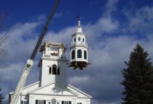
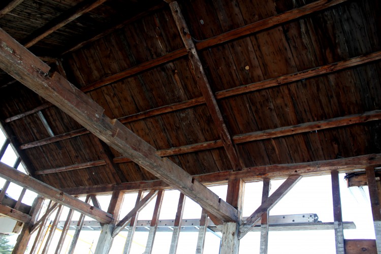
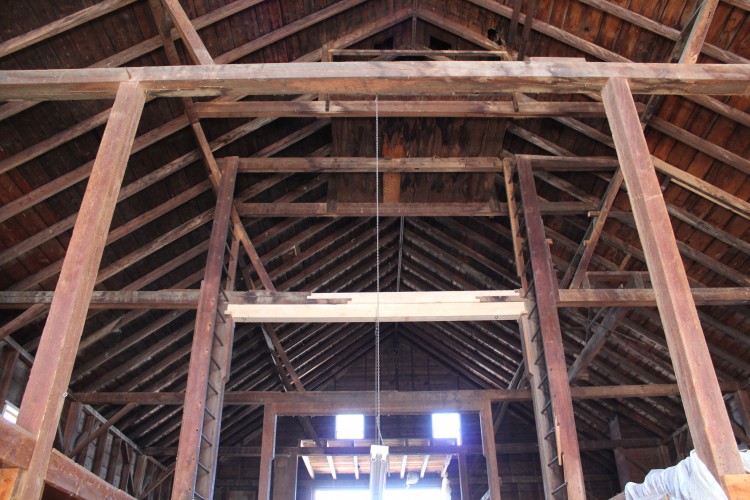
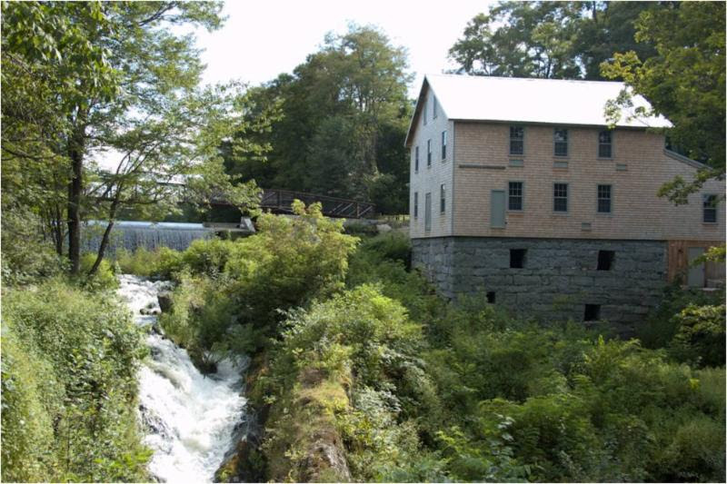
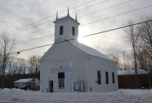
    Troy Union Church was built in 1840, in a vernacular style that combines elements of Greek and Gothic Revival. It is a modest building, 34′ x 42′, built to host the small town’s various Christian denominations, hence the “Union”. Caught up in that communal spirit, the bell tower is preparing to take a trust fall onto the back of the church. I’ve photographed a lot of buildings, and capturing a slumping wall, or humped roof can be challenging. This steeple has a model’s slouch. In fact, the center of the tie beam supporting the rear tower sags 7″ below eave height. The 10 x 10 tie beam is 34′ long, which means that there is a 7″ deflection over 17′.

    Bent 2, rear tower wall. Yellow string represents height of tie beam at eaves
    Bent 2, rear tower wall. Yellow string represents height of tie beam at eaves

    Typically, we also have trouble photographing center rot in a beam. The timber will be hollow, but look perfectly sound on its face, the only visible evidence seen through the pin’s hole in a mortise. At Troy, there is a crevass in the top of this tie beam, a 3″ x 12″ valley of rot. PTF stabilized the steeple in 2011; building a cross braced KD wall to support the failing truss. The fact that the timber was able to deteriorate that far, without dropping the entire tower, is a marvel.

    Rot Crevass
    Rot Crevass

    The design of most New England steeples is idiosyncratic. Vernacular church design is informed by regional tradition, availability of materials, individual ingenuity and a shared copy of an Asher Benjamin book. Entering a church attic can feel like entering the builder’s brain. Especially so at Troy Union Church. The main timbers are hand hewn, and the design is uncomplicated, braced wherever possible. The king post truss is without flourish, straight-sided, no flare at the head, or shoulder at the struts. The rear tower wall is a common adaptation of the queen post truss, where the tower posts take the place of the queens. Occasionally, such an adaptation can be successful, like the queen post truss in the United Church of Craftsbury Common, VT. Unfortunately, at Troy, the revised truss misses the mark. The large braces running from tie to tower post aren’t large enough to serve as upper chords, and the girt isn’t located properly to function as a strainer. That said, its hard to fault a design that supported the bell tower for more than 170 years.

    King Post Trusses Bents 3-5
    King Post Trusses Bents 3-5

    The restoration effort is led by Norma Rossel, one of 12 remaining members of the congregation. Soft-spoken, Rossel challenges one’s expectations of leadership. She is as determined as she is doe-eyed. In the Kennebec Journal, Rossel explained, “”The ladies of the church got together and said, ‘It’s up to us.’” With a population of 1000, Troy faces a challenge shared by many of Maine’s rural communities: they are in possession of a historically significant building but lack the resources to repair it. The Maine Steeples Project, of the Maine Communities Foundation, was established to address just this need. In 2011, the church was elected to the National Register of Historic Places, and received from the Steeples Project a $2,500 grant for assessment and stabilization. The church received an additional $15,000 grant from the Belvedere fund, in total raising nearly $40,000 to re-build the trusses.

    Still, it wasn’t feasible for the church to hire PTF outright. The congregation is tiny, the budget is tight, and the travel costs would be prohibitory. It will take double the funding they’ve raised already to place the trusses and complete the restoration. Fortunately, what the community lacks in local funding, it makes up for in skilled neighbor. Through connections made at a longstanding monthly potluck, Rossel found Marvin Daugherty, a caregiver and swordmaker, and Scott Pfeiffer, a farmer at the Garcelon House, a cottage industry incubator. Pfeiffer recruited Adam Joy, who raises goats at his farm and has some timber-framing experience with an uncle at Red Suspender Timber Frames, to join the restoration effort. Troy used to be called Joy, ME, and Adam descends from its founders.

    Pfeiffer and Joy sighting plumb for Daugherty, drilling pin holes
    Pfeiffer (left) and Joy (foreground) sighting plumb for Daugherty drilling pin holes

    Pfeiffer is a busy man, he and his partner sell eggs, produce wool, and maintain an organization that runs like a communal homestead. He says he is a farmer in every sense of the word, in that he farms himself out to the work that needs doing. He cannot afford to volunteer through the winter months, and neither can his fellow crewmembers. Following the model used to restore the Acworth Meetinghouse, Preservation Timber Framing will provide documentation, a repair plan, training and on-going guidance to the crew. The crew receives training and is paid a fair hourly rate that saves the church money, while spending fundraising dollars locally.

    Bent 2 frame elevation
    Bent 2 frame elevation

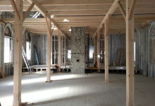
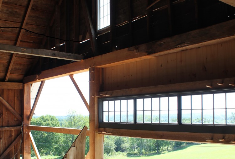
    In March, we visited the church to document existing conditions and develop construction drawings. Daugherty and Pfeiffer had already removed the sanctuary ceiling, allowing light into the attic space and making documentation much easier. We try to preserve the original design of a frame wherever possible, but the modified queen post truss at Bent 2 was under-engineered for its task: supporting half of the bell tower over an open span of 32′ (there is a 1′ overhang past either plate). We recommended rebuilding Bent 2 as originally arranged, with slightly larger timbers, and inserting a king post truss directly behind it. The new truss would be a replica of the king post trusses in Bents 3 and 4. Two bed timbers will run directly beneath the tower posts, and span from the front gable to the new truss, spreading the tower load over three tie beams (Bents 1, 2 and 3). We drew up detailed construction drawings of the repair plan, and assembled the crew in Troy.

    Fitting and Filming
    Fitting and Filming

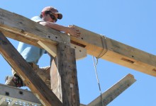
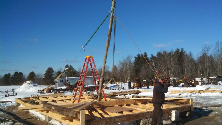
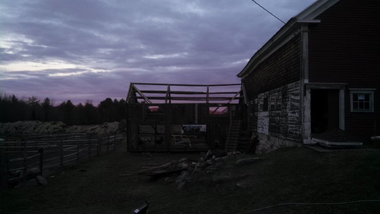
    Timber Framing isn’t particularly complicated, but it is a rare skill, unlikely to be encountered on contemporary job sites. Working with large, un-dried timbers requires a completely different conception of layout, relying on reference faces to account for variation and shrinkage. It also requires a furniture-maker’s attention to detail, a basic understanding of the forces that put beams into tension or compression, and willingness to use hand tools. Scott Lewis and Lee Hoagland met the crew at the Garcelon House, in Troy, which Pfeiffer graciously offered as a cutting yard. The crew was accompanied by sheep, goats, pigs and geese in an adjacent barn, along with their spring lambs, kids and piglets. They spent a day organizing the yard, spreading out and labeling posts, rafters, struts, braces and tie beams. They showed the crew how to establish and use reference faces and arrises, how to lay out a line and carry it around the timber, and how to lay out joinery from cut drawings. Scott and Lee laid out mortises and tenons while the crew cut. They wielded 16″ circular saws and chainsaw mortisers fearlessly. It took the crew about two weeks to complete the cutting. As soon as the weather cooperated, Scott, Lee and I returned to Troy to fit the pieces together.

    Assembling the king post truss
    Assembling the king post truss

    We were met there by two local TV crews and the Kennebec Journal. Rossel will use the completed frame to raise the money needed for a crane to put it in place. WABI Channel 5’s coverage focused on the repair process and the timber framing itself, while ABC 7/Fox 22’s coverage shows more of the church. The Kennebec Journal wrote a great article detailing the history of the building, and Rossel’s efforts with the community to raise the restoration money.

    Scott Lewis checks the fit of the half dovetail joint
    Scott Lewis checks the fit of the half dovetail joint

    Marvin Daugherty speaks in the sort of aphorisms you’d expect from a practitioner of Kung Fu and maker of samurai swords. When asked how his skills working with metal transfer to working in wood, he responded, “skill is skill and either you have the touch or you don’t” and that “it’s just being sensitive to things.” He says, “If you can be good at one thing, you can be good at a lot of things.” Talking to Daugherty, I learned that a person can have Kung Fu in any craft that requires training over time, and that the singular association with martial arts is an American invention. I must not have a good appreciation of Kung Fu, because what impressed me, visiting the jobsite in Troy, was how quickly Daugherty and the rest of the crew had picked up timber framing. After training with Scott and Lee a handful of times, Pfeiffer, Joy and Daugherty had re-constructed the entire rear wall of the bell tower and a beautiful king post truss. If you are interested in the efforts to complete the restoration, please visit the Troy Union website.

    More photos, below:

  • After Fire, a Family Doubles Down on Preservation

    After Fire, a Family Doubles Down on Preservation

    Restoring an historic building takes a lot of stamina. The sense of warmth and meaning one feels within a restored structure comes from the labor invested by the craftspeople who built it and the experiences of the community that used it. Once complete, the Steiner-Truesdale residence in Newfields, N.H.,will reflect not only a century of life as a church, but also the owners’ dedication to restore it as a family home, twice. In April, a fire destroyed much of the interior, an 8-year long labor of love for owners Jack Steiner and Kimberly Truesdale. In November, PTF began its role in the home’s re-restoration.

    Ribs and Roof system
    Ribs and Roof system. Photos by Brian Cox

    Newfields’ Sacred Heart Church was built in the 1880’s — a transition frame, 40′ wide by 80′ long. Five interior timber bents were constructed from a pair of posts, a pair of steeply pitched rafters, two pairs of ribs and a collar tie. The lower ribs brace the posts to the rafters and the upper ribs brace the rafters to the collar tie. The ribs are let-in and bolted, rather than mortise-and-tenoned, reflecting the dominant technology of the period. A tie rod takes the place of a tie beam, tying the eave walls together. Had the church had been built in stone, in the original Gothic style, buttresses would have provided the support necessary to counter the outward thrust of the rafters. The roof system is substantial, consisting of the principal rafters let in with principal purlins and infilled with common rafters. The balloon studs run from sill to plate, and are spaced approximately 20 inches on center. The plate consists of doubled 2x stock, which is mortised and fit onto a tenon at the top of each of the posts.

    Stopped chamfer detail
    Stopped chamfer detail

    PTF was hired to rebuild a second floor that had been destroyed in the fire. The height of the floor was determined by the tie rods, so that the rods could be enclosed between the 10″ high floor joists. Two 8″ x 10″ x 60′ floor girts run parallel to the eaves, supporting the joists. Five pairs of posts, in line with the bents, support the girts. The posts rest on first-floor girts, or carrying timbers, parallel to the girts above. The carrying timbers rest on masonry piers set directly beneath the posts, point-loading the interior structure to ground. Ultimately, the entire frame will be exhibited within the living space. The timbers were planed, and the crew matched a chamfer detail from work that Jack completed: a 1″ chamfer on all posts and girts, a 5/8″ chamfer on joists and braces, stopped 1 1/2″ from joinery.

    Once onsite, Brian and the crew’s first step was to unload and organize the stock. In addition to the six 8″ x 10″ x 20+” stock required to create the second floor girts, there were more than seventy-five 4″ x 10″ x 12′ joists, ten posts, and sixteen white oak braces. The crew, Brian, Shawn and Seth, took half a day to lug lumber, moving the timbers along a pick through the window, and another day just to organize it all. Organizing timbers is like sharpening chisels –t ain’t romantic, but it’s necessary to a well-run job. A clean and well-organized job site makes a big difference in the efficiency and accuracy of the good stuff, such as cutting joinery.

    Shawn, girt timbers, and Shawn's breath
    Shawn, girt timbers, and Shawn’s breath

    All the joinery was cut and test-fit on sawhorses prior to installation. Each 60′ second floor girt was made up of three 20+’ sticks joined with two bladed scarf joints. Cutting a frame indoors in November sounds like a pretty cushy job, but because the floor girts and joists were so long and still green, the crew wanted to do everything possible to prevent them from corkscrewing, and this meant working without heat. With the heat off, the timbers would dry more slowly, ensuring their stability. Furniture makers will sometimes avoid kiln-dried wood, instead stacking freshly-cut boards evenly; plenty of air flow lets the boards dry naturally over the course of years.

    Thanks, Grandma! the scarf fits perfectly.
    Thanks, Grandma! the scarf fits perfectly.

    Each of the posts was connected to the floor girt by two braces. After cutting, all of the brace joinery, as well as the six scarves, were fit and laid out on sawhorses. In order to prevent the joinery from opening as the timbers dried, the crew decided to draw-bore all the joinery. Draw-boring is a joinery technique in which the pin hole in the tenon is placed 1/8″ closer to the shoulder of the joint than the pin hole in the mortised piece. A tapered pin is driven through the holes, squeezing the mortise and tenoned pieces closer together.

    Lee and Scott assist with assembly
    Lee and Scott assist with assembly

    After the pinholes were drilled, the crew erected two towers of staging along the center of the church. Using a chain fall, they lifted the three pieces of one girt into place, and re-assembled and pinned the girt on the staging. Next, they righted the posts and threaded their feet through holes in the first floor, maneuvering the posts into mortises on the carrying timbers below. Due to variation in floor depth, the posts were buried 9 1/2″ – 22″ below the surface of the first floor. The crew squared and plumbed the posts and temporarily braced them to the exterior walls with 2x lumber. Then the oak braces were fit into their mortises and pinned.

    Second floor girt in position, and blurry
    Second floor girt in position, and blurry

    Three one-ton chain hoists were needed to raise the assembled 50′ floor girt into position, 4 1/2″ above the post shoulders (and 1/2″ above the ends of the tenons). The girt just kissed the 1″ round tie rods, which ultimately run between the 10″ high floor joists. When the weight was released from the staging ledgers, those ledgers sprung up, and as the ledgers were removed, their wedges popped out with a “ping.” Coordinating efforts, the crew released the chain falls and slowly lowered the girt onto the five post and eight brace tenons. Then they pinned the joinery. For the second girt: rinse, and repeat.

    Floor framing, resurrected
    Floor framing, header visible near window, far left

    The second floor is supported by more than seventy-five 4″ x 10″ x 12′ joists, which were lifted into place using a winch. At each of the eight windows, the crew created a window well by inserting a 6″ x 10″ header between the joists adjacent to the window, so the top of the window and the arched trim can be seen from the first floor. The header fit into a pocket into the adjacent full-length joists, and the short joist sits in a pocket in the header.

    With the framing now complete, the Steiner-Truesdale family can finish their adaptive re-use of this Gothic Revival beauty. We were truly saddened to hear of the fire, and now we are honored to be part of this building’s journey.

    Completed framing, from below
    Floor framing, from below
  • Kitchen of the Community

    Kitchen of the Community

    New Hampshire Preservation Alliance recently released an inspiring video about the restoration of the Acworth Meetinghouse. Built by Elias Carter in 1821, the Acworth Meetinghouse, with its double lantern spire, is a masterful representation of historic building craft. In 2008, the steeple and undercarriage were repaired by local craftspeople trained and supervised by PTF in techniques unique to steeple repair, and timber framing. In 2011, the Acworth model won a Preservation Honor Award from the National Trust for Historic PreservationNHPA’s video is an inspiring glimpse into the effort invested to repair this “kitchen of the community.” Next year, we’ll be drawing upon lessons learned in Acworth to help the community of Troy restore the trusses of the Troy Union Church (fb). 

    Feature photo courtesy Acworth Meetinghouse Restoration Project


  • Stylish Scarfs for Summer

    Stylish Scarfs for Summer

    Joe McAllister, fitting Bent 6. Welcome back, Joe!
    Joe McAllister, fitting Bent 6. Welcome back, Joe!

    On Monday, the Pennell crew erected the ell by hand. They had a roustabout on-site, which is like a more portable, telescoping gin pole, but the bents were light enough to raise with a crew of four. The ell, a drop-tie frame built in the mid-1800s, was dismantled earlier this spring during the first phase of Pennell House repair. The frame parts were transported back to the shop in Berwick, repaired, and test fit. Our most recent North Bennet Street School intern, and newest employee, Joe McAllister devoted his final school project to the cutting and joining of two additional bents to prepare the frame for re-use as a contemporary kitchen.

    East gable, dismantled
    East gable, dismantled

    Following the ell, repairs to the house were extensive. The frame was lifted on steel I-beams in order to replace the foundation and completely rebuild the undercarriage.  Seven of the eight house posts needed repairs, two of which required full replacement. The first floor studs of the north, south and east walls all required lap repair or replacement. Along the north eave, all three second floor girts and eight of their associated braces were replaced. Ultimately, the entire east gable bent was completely dismantled, repaired, and rebuilt, while the rest of the building was left standing. See “before” picture, above, and “after”, below.

    East gable attic, reassembled
    East gable attic, reassembled

    Revisiting the job-site this week, I realized that the diversity of joinery matched the broad scope of repairs. The decision to use a particular scarf, spline or lap joint is dependent on a number of factors including location, level of deterioration, difficulty of installation, historic significance, and whether or not the joint will be in tension, compression, or subject to twisting. For joinery enthusiasts, I’ve recommended Historic American Timber Joinery, by Jack Sobon, and I’ll recommend it again; it is the definitive reference manual for those pursuing traditional repair of historic timber framed buildings (I’ve linked to a PDF, if you want a hard copy, it’s worth ordering one from the Timber Framer’s Guild). On a hybrid job like this one, combining preservation, energy retrofitting and adaptive re-use, we used both traditional scarf techniques like those in Sobon’s book, and contemporary approaches, like splines and free tenons. Paradoxically, sometimes the newer repair techniques are able to preserve the most original material.

    Bladed scarf, you old so-n-so
    Bladed scarf, you old so-n-so

    If you visited our site before, job or web, you’ll know that our bladed scarf is an old standby.  It works well for post fixes, because the keys prevent the joint from slipping or twisting under outward pressure. The outward thrust of the rafters from above, in combination with the possibility of a rolled sill, and the inward tension of the tie beams and tie girts, means that a post scarf should have some means of “locking” to prevent slippage.  This could also take the form of an under-squint (see below) but in this instance, we prefer the square-bottomed keys of the bladed scarf. These multi-directional forces are what make a simple lap joint inappropriate for post repairs. We expect our repairs to last for as long as the building has already been standing. Over the course of 150 or 200 years, there may be shifting in the foundation, or deterioration in a sill, that would complicate the pressures acting on our post fix.  A bladed scarf joint is designed to withstand those forces, so that in 100 years, if a sill needs to be replaced, the post foot and associated repair can remain intact. (I hope Athena, protector of woodworkers, notices that we strive only to double the lifespan of a building, we don’t expect to triple it.)

    Halved and bladed scarf in the undercarriage
    Halved and bladed scarf in the undercarriage

    A bladed scarf is also used to repair an unsupported section of sill.  When a sill, summer beam or floor girt is supported on posts or piers, rather than a full foundation wall, it needs a repair that can support itself and prevent sagging without introducing metal brackets or plates. The introduction of big plates of metal, especially in potentially moist environments, like a basement, risks the danger of condensation and its dreaded associate, rot. While a lap joint may be sufficient for many sills, on stable, continuous foundations, the keys in a bladed scarf give it compressive strength perpendicular to the joint.

    True-Randall Tie Beams
    True-Randall Tie Beams

    In a timber under considerable tension, such as a tie beam, a bladed scarf joint may not be appropriate. The joint has considerable resistance to compression and twisting, but relies on pins and friction to prevent spreading. We’ve long used a tabled, wedged joint to prevent spreading in tie beam repairs, but at the True-Randall Farm in Montville, we encountered a stop-splayed, under-squinted and wedged scarf that had been used to extend the length of tie beams by more than ten feet. The barn was moved over a hundred years ago, and the joints had loosened, but held up considerably well under the strain of a crumbling mid-century concrete block foundation. The biggest threat to a barn’s frame is water infiltration. When tying joints fail, allowing plates and rafters to spread, roof leaks can result, leading to water infiltration that will accumulate on any available horizontal surface: plates, girts and, often, all the way to the bottom of the frame, at the sill.

    Stop-splayed, undersquinted and wedged scarf in the east gable tie girt
    Stop-splayed, undersquinted and wedged scarf in the east gable tie girt

    We used this stop-splayed, under-squinted, and wedged scarf joint to repair the east gable tie girt. The east gable bent contained two tying timbers: a tie beam above, which runs from plate to plate and required full replacement, and this tie girt, which supports the second floor joists, and is fully supported by studs from below. The under-squinting is the little angled cut two inches from the top and bottom faces of the timber; this angled cut also helps to mechanically “lock” the joint, and prevent twisting.

    Slope-shouldered and under-squinted bolster.  Note free tenon in second story girt, above.
    Slope-shouldered and under-squinted bolster. Note free tenon in second story girt, above.

    Elsewhere in the house, we found another instance of under-squinting, in a slope-shouldered bolster used to repair a post. This was a really cool fix that was probably installed sometime after a renovation that involved hacking out the interior faces of the posts, so that they wouldn’t intrude on the interior wall plane (how dowdy and old-fashioned!).

    Mortises: Exposed!
    Mortises: Exposed!

    This assault on the frame resulted in some posts being sliced in half, immodestly revealing their joinery. Unfortunately, this hackery also removed the bearing shoulder of the post which formerly supported the ends of the second story floor girts. The bolster above was installed around 100 years ago to support the end of one of these girts.

    North eave, center girt, before.
    North eave, center girt, before.

    Three second-story girts along the north eave were rotted and needed full replacement. The second floor joists fit into cogs cut into the interior faces of the girts, and stayed put during installation of the repairs. Likewise, the four north eave posts could not be moved (the east gable post was replaced in full, but needed to be installed before we replaced the girts). The conditions created by a standing frame required that we use a free tenon or spline connection to repair these elements. We cut the girt to length, shoulder to shoulder, and cut a slot in the underside of the timber the full length of the free tenon.

    Free tenon repair between girt and post. Extended mortise in post is plugged.
    Free tenon repair between girt and post. Extended mortise in post is plugged.

    We install the girt between the standing posts, and then insert a free tenon into the slot. Then we slide, or pry, the tenon laterally so that in engages with the accompanying mortise in the post. Lastly, we plug the gap that is left in the girt. In those instances where the posts are in better condition, the post mortise can be extended. The free tenon is inserted below the girt and slid up into the slot. Then the extended mortise in the post receives a plug (see above).

    Half lap, and partial bladed scarf joint
    Half lap, and partial bladed scarf joint

    Seven of the house’s eight posts required repair or replacement. In each case, we preserved as much original post material as possible, resulting in some fairly idiosyncratic fixes. In the one pictured above, an interior corner of the post had been removed in the previous “renovation” and required a slightly more complicated version of the bladed scarf joint.

    Bridled half lap repair in south plate
    Halved and bridled scarf repair in south plate

    The twin threats of squirrels and rot wreaked havoc on the east ends of the north and south plates, requiring a scarf repair for each of them.  Plates endure considerable torque, created by the outward thrust of the rafters and inward tension of the tie beams. Lee used a halved and bridled scarf on the ends of these timbers in order to retain the most material, and prevent twisting or rolling.

    Splining the ell plates
    Splining the ell plates

    The original ell plate was full length, and in good condition.  The plans required an extension of the ell by two bents to accommodate a contemporary kitchen, but we didn’t want to remove any more original material from the plate than was necessary. The plate had its own interesting joinery, worth preserving, in the form of a rabbet along the top interior edge, that caught the birdsmouth on the rafter tails. A traditional scarf joint would have required the plate to be cut back as much as two feet. Instead, Ed designed a spline-joint, that connected the original plate, the new plate extension, and the post, all in one (above).

    South eave stud repairs
    South eave stud repairs

    Three quarters of the first story studs required repair or replacement. Where feasible, we used a simple half-lap repair on the athlete’s feet of rotten studs. The half lap, instead of a full length stud replacement, allowed us to replace studs with tenons on either end, even when the stick was captured by a sill below and second-story girt above.

    Rafter foot and tie connection. This one wins worst.
    Rafter foot and tie connection. This one wins worst.

    Often, we encounter bolts and L-brackets employed to little effect. Sometimes, these metal band-aids do more harm than good, due to the introduction of large plates of metal, against which water can condense and be held against the timber, or by creating a tensive or compressive force where it does not belong. There are instances, however, where a metal bolt or bracket is the best solution. The tie beam ends at the Pennell House were one such case. Each of the 5 remaining tie beams showed various levels of rot at either end, outside of the plate and the rafters’ birdsmouth. Other than the east gable tie, none of ties were rotted enough to require a scarf repair. However, the joinery on the end of the tie, the angled cog capturing the rafter’s birdsmouth, needs to resist considerable force, especially from the rafters that carry the cupola.

    Rafter tie connection, repaired with bracket and bolt
    Rafter tie connection, repaired with bracket and bolt

    We wanted to ensure that the tie beams would continue to prevent the bottoms of the rafters from spreading. Ultimately, we used a combination of 3/4″ threaded rod, and Simpson-brand L-brackets to create an economical solution to this pervasive, but relatively minor, problem.

    Preservation work can be frustrating, because every building is unique, and every problem is interconnected with others. The lack of a universal solution makes preservation work almost as difficult to estimate as it is to execute. Fortunately, it is the very same combination of variety, unpredictability and creative problem-solving that makes this work so much fun.

    Teamwork! Look what fun Joe, Lee and Scott are having!
    Teamwork! Look at what fun Joe, Lee and Scott are having!

    For more photos of our process at Pennell; please visit our Flickr page.

  • Dismantling the Pennell Ell

    Dismantling the Pennell Ell


    Pennell Ell Frame
    Pennell Ell Frame

    Over this long spring, we’ve been so elbow deep at the Pennell project in Brunswick that I’ve been remiss in writing about it. The James Pennell House, on Pennellville rd., is a two-story Greek Revival house built in 1838. It is a high-style home, with the later addition of cupola and ell. The project is a collaboration with Taggart Construction, which specializes in green building, and the architect Elizabeth Newman. PTF was hired to repair extensive damage to the timber frame, and we are glad for the opportunity to work on another project that combines historic preservation and high performance energy efficiency.

    Another post, with a wedged half dovetail
    Another post, with a wedged half dovetail

    After an initial assessment, our first step was to document, tag and dismantle the attached cape ell.  The damage to the ell, and to the undercarriage of the house it was attached to, led to the conclusion that the ell would be most efficiently repaired on the bench.

    Ell, being prepared for crane day
    Ell, being prepared for crane day
    Bent 2 post-tie connection, wedge removed, note original label
    Bent 2 post-tie connection, wedge removed, note original label, “2 East,” written in crayon

    Both the house and ell reflect later developments in timber frame design. Regular readers of this blog will recognize the drop tie secured with a wedged half dovetail like the one found in the carpenter’s shop.  Unlike the carpenter’s shop, however, the eave walls are studded, rather than framed with horizontal nailers.

    Gable end, note rafter-plate connection
    Gable end, note rafter-plate connection

    The undercarriage was badly rotted and required complete replacement, in addition to the repair of a couple post feet and replacement of two tie beams. The plates, however, were full length, 32′ and in good condition. The rafters had a birdsmouth at the foot which fit into a rabbet cut along the interior edge of the plate.

    Crane removal of full-length plate
    Crane removal of full-length plate

    Crane day went smoothly, largely due to our ability to dismantle the purlins and rafters by hand the afternoon beforehand. The purlins were full length, but thin, and could be slid down the rafters and lowered to the ground on ropes.  The rafters were short and could be reached by a pick that was laid across the tie beams.

    Butterfly bolt detail, wedged end inside ell
    Butterfly bolt detail, wedged end inside ell

    The most unusual feature of the frame was the hardware connecting the ell to the main house frame. The ell’s bent one tie beam was bolted to an eave girt in the main house and one of the ell rafters was bolted sequentially to the adjacent studs on the house’s second floor. The hardware was an older style, consisting of a long bolt which was drilled through the two framing members, with a head on the house side and the other end extending a couple inches into the ell.  A slot mortise was cut into this tail end, and a wedge was driven through the slot and peened over. The adjacent ell gable sill and eave house sill were also bolted together in this manner. Arron referred to this as a butterfly bolt, and noted that it was an older technology in comparison with the design of the rest of the frame. Removing these bolts was a process of delicately straightening the wedge, knocking it back through the slot mortise, and then slamming the bolt back into the house. I remember the sound of the bolt falling to the concrete foundation inside the house as a terrifically satisfying clatter.

    Giggling guys
    Giggling guys

    After the ell was fully dismantled and transported back to the shop for repair, the crew cut two additional, identical, bents that will extend the ell by 22′ for use as a contemporary kitchen. The combination of renovation, frame preservation and green building technologies has been a fascinating learning experience. Repairs to the main house have been complicated, intensive and are good fodder for future blog posts.

    For more photos of the Pennell House and the ell frame dismantling, visit our Flickr album.

  • Todd Farm Barn: Guest post by Brian Cox

    Todd Farm Barn: Guest post by Brian Cox

    Todd Farm Barn.  Photo Jessica MilNeil
    Todd Farm Barn. Photo Jessica MilNeil

    With spring in sight, it’s easy now to look back with pride at the frigid months spent repairing the frame of the Todd Farm Barn. Shawn Perry, Jesse Turgeon, Reese Crotteau and Brian Cox worked diligently to repair posts, tie beams and undercarriage of this large transitional frame in Rowley, MA. When all contractors have completed their repairs, the barn will expand space for Todd Farm antiques. Todd Farm flea market opens this Sunday, April 13th (experienced treasure hunters recommend getting there early, 6 am early). Below, Brian illustrates and describes PTF’s repairs, including photos of some sweet tie beam scarfs.

    The Todd barn measures approximately 45’ x 65’.  It dates from the early twentieth century and is a transitional frame, with little joinery.  With the exception of the girts in the undercarriage, most frame elements are nailed.  It has doubled top plates of nominal lumber, nailed together, studded eave walls, and as you would expect, studded gable walls above the tie beam.  PTF was contracted to complete structural work, illustrated in the images below.

    North eave looking west. Photo by Brian Cox
    North eave looking west. Photo by Brian Cox

    Lifting brackets were placed on each of the seven posts along the north eave, as the entire length of sill needed to be replaced due to extensive rot.  Cribbing piles were placed under the center of the lifting brackets and jacks and jack posts were installed.  The barn was lifted only a minimal amount in order to cut the nails holding the studs at the sill level.

    North eave sill, one half of a bladed scarf joint.  Photo by Brian Cox
    North eave sill, one half of a bladed scarf joint. Photo by Brian Cox

    The existing sills along the north eave were approximately 6”x 8”, with a 2” ledger on the inside face, which supported the joists. We repaired this sill using a bladed scarf joint, with the blade, or table, being 24”. The sill timber measures 8”x 9”. We chose to install an 8”x 9” based on the dimensions of sills in place in the remainder of the barn.

    North eave scarf, where sill timber #2 meets sill timber #3.  Photo by Brian Cox
    North eave scarf, where sill timber #2 meets sill timber #3. Photo by Brian Cox

    There were a total of five sill timbers cut and installed along the north eave.  A marriage mark made in pencil was used for easy identification purposes.  Upon completion of the sills being cut, they were fit and drilled with a 1” ships auger bit. Hardwood pins were driven after stringing the face of the sills and a straight line on all five timbers was achieved. Mallet marks are visible, where gentle coaxing was needed to drive the timbers into position.  Knots prove to be great driving locations, when available. 

    Cribbing piles in basement.  Photo by Brian Cox
    Cribbing piles in basement. Photo by Brian Cox

    We built piles of 6”x 7” hemlock cribbing to support steel I-beams, which were used to hold the joists and girts off of the foundation while a new foundation wall was built. The new foundation was a poured concrete wall topped and finished with brick. Hydraulic jacks placed beneath the steel were used to level each bay while eave posts were lifted using jacks, brackets and dead men.  A 2″x 6″ ledger was fastened across the posts, and timber-locked to each stud in between. This ensured that the studs were lifted along with the posts and girts.  Where viable, we left sheathing and clapboards in place.  This makes the wall a little more difficult to lift because the sheathing and clapboards hinder fine tuning.

    East gable tie beam, from exterior.  Photo by Brian Cox
    East gable tie beam, from exterior. Photo by Brian Cox
    On the east gable, we built wedgelock scaffolding to the tie beam level. Upon labeling and demo of sheathing and clapboards, we discovered what an old colleague of mine would refer to as “termites holding hands”, or in this case, ants holding hands. We found, as illustrated in this image, significant ant damage. Many braces and studs above the tie beam no longer reached the tie beam and, where they did, there was no structural surface remaining that could accept any compression forces. At this level of rot, the sheathing in this area was structural. This damaged material was removed and, where sound material was encountered, a 24” bladed scarf was cut and a new corresponding bladed fix was installed.    
    East gable tie beam fix, from inside.  Photo by Jessica MilNeil
    East gable tie beam fix, from inside. Photo by Jessica MilNeil

    One end of the fix and original material shown in above image.  The studs in this gable were cut away and compression blocks and sisters were added.  Similarly dimensioned fixes and sisters were installed.

    Bent #4 floor girt repair.  Photo by Brian Cox
    Bent #4 floor girt repair. Photo by Brian Cox
    We uncovered additional rot in the floor girts in the barn. The girts running eave-to-eave were continuous and the drive girts were discontinuous.  Temporary deadmen were used to stabilize the joists adjacent to the girt repair.  The drive girt between bents #4 and #3 was replaced concurrently.  Beneath the girt, we installed a permanent dead man, topped with two crossed oak bolsters. This configuration was placed beneath each drive post point load.  A lead barrier was placed between the concrete footer and the post bottom at each of these locations.
    Bent #5 tie beam fix.  Photo by Jessica MilNeil
    Bent #5 tie beam fix. Photo by Jessica MilNeil

    Water infiltration at the cupola lead to deterioration of the tie beam at bent #5. A tie beam fix, with a bladed scarf on each end, replaced the center segment of the existing tie. A 6” x 7″ bolster was then placed under the tie beam fix. This bolster is also in place at bent #4.  There was a loft above this area that was removed prior to work commencing. Note the lack of bracing from drive post to tie.  There are braces from the eave posts to the tie, and these are nailed in place, rather than connected by mortise and tenon. The rafters are full length from peak to eave.

  • Watch “Reviving the Freedom Mill” on MPBN, Thursday, March 6, at 10:15 pm

    Watch “Reviving the Freedom Mill” on MPBN, Thursday, March 6, at 10:15 pm

    Reviving the Freedom Mill, photo courtesy Tony Grassi
    Reviving the Freedom Mill, photo courtesy Tony Grassi

    Maine Preservation writes:

    When Tony Grassi takes a crazy gamble to rehab an abandoned mill, he inspires both skepticism and hope that its revived bond with the river will breathe new life into the town of Freedom, Maine.

    With the help of a colorful team of builders, masons, engineers and architects, he sets out to reconstruct a forgotten historic treasure. Can his 21st century vision of preservation re-power this rural community, which is now welcoming a new generation of young farmers?

    Watch “Reviving the Freedom Mill” on your local MPBN station on Thursday evening, March 6, at 10:15 pm.  This was one of PTF’s biggest and most inspiring projects in the past few years.  A significant portion of the crew devoted their time and energy to the project, staying in Freedom, away from their families, during the months spent on the project.  We were honored that the project was a recipient of the 2013 Maine Preservation Honor Award and are especially thrilled that the crew’s efforts were captured in such an engaging documentary.

    View more photos of the finished project, here

  • I’ll take a Gin Pole, straight up.

    I’ll take a Gin Pole, straight up.

    Lee on Deck
    Lee on Deck

    Here’s one to please our 11-year-old selves, and the folks over at Low-Tech Magazine: we raised the Carpenter’s Shop using a gin pole.  This is a simple and traditional method for raising a timber frame by hand, and straightforward solution to a site with little crane access.  It’s constructed from a long, straight pole with a block and tackle hanging from the top, and two guy lines (in our case, come-alongs) that help to counter the weight of the pole and the timbers, and locate the posts in their mortises.

    This is an eave assembled on the deck.  A bent assembly isn't pictured, but looks similar, rotated 90 degrees
    This is an eave assembled on the deck. A bent assembly isn’t pictured, but looks similar, rotated 90 degrees

    After test-fitting the eaves, we assembled the first bent (like a bread slice of the timber frame, parallel with the gable) flat on the deck so that the post tenons were hanging over their corresponding mortises – so that, when rotated to vertical, the tenons would “tip” into their holes.  The pieces of the bent were fit together so that the tie beam was placed towards the center of the deck and all the exterior reference faces were facing up.  The bent was fit, measured, bound, remeasured, and then pinned and wedged.  Each bent has two ascending and two descending braces, creating an especially stable and sturdy frame.  What original wedges couldn’t be reused were cut from seasoned white oak.  It was satisfying to knock the wedges in tight, locking the half dovetail tenon at the end of the tie beam to the sloped shoulder of the post’s complimentary mortise.  Ah, wedged half dovetails.  We screwed stop blocks to the corners of the sill so that the post feet couldn’t slip off the deck as the bent was raised.  We also screwed two 2x8x16′ pieces of KD to the exterior face of posts, at the top of the post, so that they could be used as kickstands once the bent was nearly vertical.  That completed the first bent assembly.

    Lee cut a maple sapling that was at least 18′ long, which is half again as tall as our posts (we realized through trial and error that this could have even been a little longer, but you could realize that sooner using a physics textbook). He attached a block and tackle to the top end of the sapling (again, if one was so inclined, we could calculate the exact number of pulleys needed to create the mechanical advantage to pull the bent up using human-power, but we had a tractor, so we used the block and tackle that Lee had).  Directly beneath the block and tackle connection, we attached two 24′ come-alongs.  That completed the gin pole assembly.

    Gin Pole in Tension
    Gin Pole in Tension

    We screwed a U-shaped block to the deck at the foot of the gin pole, near the center of the frame, to keep the foot from slipping out of place.  The opposite ends of the come-longs were secured to the rear corners of the deck, so that the gin pole come-alongs and block and tackle created a peace sign on the deck (a peace sign without a circle, and with two extra long come-along legs).  Scott and I lifted the gin-pole into a nearly vertical position, while Lee loped back and forth, tightening the come-alongs as we raised the pole.  Working the come-alongs allowed Lee to center the top of the pole precisely over the bent.  When the pole was leaning forward so that the block and tackle hung directly over the center of the tie beam, Scott pulled down tight on the block and tackle, connected the hook at its base to the center of the tie beam, and pulled down on the free end of the rope (pictured above).  This created a stable triangle of opposing forces (block and tackle, come-along and come-along), securing the gin pole in place about 10 degrees from vertical.  This completed the raising of the gin pole.

    Scott pulled down on the raising rope, and, nothing happened.  If we had not had the tractor at our disposal, we would have needed a block and tackle with more pulleys, and a rope with less stretch.  As it was, we hooked that sucker up to a tractor, corrupting the purity of a hand-raising.  For shame! Anyways.  We attached the rope to the front of the tractor as high and as close to the top of the gin pole as feasible.  I reversed the tractor and lowered the arm with all the grace of Kevin Bacon in Footloose as Scott monitored the post feet and Lee let out the cable on the come-alongs, incrementally.

    First Bent, raised
    First Bent, raised

    Once the bent was lifted past 45 degrees, I set the brake, re-tied my shoelaces, and Scott and I used the 16′ pieces of KD attached to the tops of the posts to lift the bent to vertical, and seat the tenons in their mortises.  We screwed the KD kickstands into the eave sills, and stopped to admire our work. With the kickstands in place, we were able to plumb the bent precisely.  When we satisfied with the bent’s location, we moved the gin pole, and prepared to raise the second bent.

    Lee in Tee at 10 degrees
    Lee in Tee at 10 degrees

    The gin pole was not the only low tech technology employed at the Carpenter’s shop.  Lee used an adze to cut the tenons of the first floor joists, allowing him to work in a tee shirt in single digit temperatures.  After the bents were raised, we used a water level to level them.  On sunny sites, it’s sometimes easier to use a water level than a laser.  If you want to know more about either of these methods, please let me know.

    New blue water level hung at reference corner
    New blue water level hung at reference corner

    Sometimes the oldest technologies provide the best solution for the job at hand.  From wedges and ramps to pulleys, I am surprised at how right my physics teachers were about the ubiquity of simple machines.  When applied purposefully, with careful consideration, these approaches can be safer, simpler and cheaper.  While I appreciate the romance associated with historic contraptions, ultimately, romance is not the reason we employ them.  These technologies are selected when they are the most functional option for the job at hand.  We were just lucky to have some fun with them up in Poland.

    Tradition
    Tradition! – tra-di-tion!
    Completed frame
    Completed frame


  • It really tied the barn together

    It really tied the barn together

    True-Randall Farm Barn, roof system from rear loft
    True-Randall Farm Barn, roof system from rear loft

    Tie Beams are the defining component of a timber frame.  They tie a barn together better than The Dude’s rug ever could. A tie beam crosses the gable at or below the plate (eave) level, and prevents the eave walls from spreading under the outward pressure of the rafters.  Tie beams, more than any other element, identify the style of timber frame, be it English-tie, drop-tie, or interrupted.  While a tie beam alone can’t date a building, these designs are associated with particular time periods; the English tie with the 18th and early-19th century, and the drop-tie with the 19th century (in Maine). I’ve written elsewhere about these impressive framing members, and the relative pros and cons to their design (Historic American Timber Joinery, by Jack Sobon, and made available by the Timber Framers Guild, is a fascinating and exhaustive source of joinery information).  Below, I’m going to describe what goes into repairing one, in a standing building.

    The owners of True-Randall Farm have a strong preservation ethic, combined with a desire to have their property serve their contemporary needs.  They walked a fine line throughout the project, preserving every original, functional framing member, while installing a clean, contemporary kitchen in a long re-muddled connecting ell (preserving any remaining original framing even here, even though invisible).  The house and barn on either side retain their original design and artifacts, as well as transitioning beautifully into a functional modern kitchen.  The barn is visible through a sliding glass wall in the kitchen, where the expansive timber frame and associated repairs can be admired during meals.

    Scott, laying out fixes
    Scott and Lee, laying out fixes

    The repairs to the barn were extensive.  We replaced sills, foundation and drainage, and shored up the undercarriage. Two posts were replaced, along with their adjacent loft girts.  Unfortunately, pernicious rot in the tie beam was invisible until exterior sheathing was removed to replace one of the drive posts.  One of the advantages to timber frames is that a beam can rot extensively before losing functionality, or before the damage becomes visible.  This is also one of the disadvantages.

    The True-Randall barn has endured a history of alteration and adaptive reuse long before PTF or the current owners arrived.  According to the history researched and written by owners George and Karin Look:

    In 1889 the barn was moved to its current position and connected to the house by an ell. Local history indicates that it was rolled across the road using oxen and logs and that a small American Elm run over during the move stood back up and grew into a giant tree in front of the barn. The roof was removed before the move and roof elements, including the purlins, were used in building the deck for the barn, which was converted into a bank barn. At the time of the move an original eave wall was moved to the east 6 feet to increase the size of the milking parlor to accommodate the new, larger breeds of dairy cows that were becoming popular at the time. Also, the new roof was built with higher pitch to allow for storage of more hay. The barn was in use in a dairy operation until the 1970s.

    Series of c.1899 stop-splayed, underquinted and wedged tie beam extension scarf
    Series of c.1899 stop-splayed, undersquinted and wedged tie beam extension scarf

    In order to extend the barn 6′ east, a scarf joint was cut into the east end of each of the tie beams.  As its name suggests, a tie beam functions in tension and any scarf along its length must equally resist those forces as any link in a chain.  PTF’s commonly used halved-and-bladed scarf joint (p. 47, Sobon) is a great joint, but wouldn’t necessarily be effective here.  The barn-wrights in 1889 used a stop-splayed, undersquinted and wedged scarf joint (p. 49, Sobonto extend the tie beams by six feet and accommodate a new milking parlor.  The two inch wedges in this scarf push the two halves of the joint together, countering the outward thrust of the rafters.  This wedged key resists that force better than the shear strength of one inch pins (as would be used in other scarves).  Additionally, the wedges can be driven into the key with seasonal and yearly wood shrinkage.  This adaptive quality of wedges is employed elsewhere in timber-framing, such as the wedged-half-dovetail joint used at the ends of the Carpenter shop’s drop-ties, and in the wedged-half dovetail at the bottom of the king post in the Abyssinian Meetinghouse.  The beauty of the wedge in a king post truss is that, being oriented vertically, the wedge drops deeper into the joint as the wood shrinks, automatically tightening the joint, like a glacially-paced Rube Goldberg contraption.

    Lee, Chuck and Scott strategizing on staging
    Lee, Chuck and Scott strategizing on staging

    The front gable tie beam was badly rotten due to water infiltration.  Located at the top of Randall’s hill, the front of this barn endures an inordinate amount of wind-driven rain, indicating the window directly above as the most likely culprit.  The 18′ section of punky, rotten wood extended from the center of the drive to within 8′ of the rafter-tie-plate connection.  We were fortunate that the rot didn’t extend to the English tying joint at the eave, as the repair would have required more complicated rigging and joint-cutting.

    One scarf half, on the existing tie beam
    One scarf half, on the existing tie beam

    As it was, we built 3 levels of structural, wedge-lock staging across the plane of the front gable, extending from 7′ of lawn adjacent the gable into 7′ of the first bay of the barn.  By crossing the upper ledgers of the staging with heavy, 8×8 rigging timbers, we were able to pick up the tie at two points, directly outside of the rot.  The studs above were stabilized with a 2×10 hemlock ledger screwed across their faces.  After the rigging securely supported the tie beam and framing above it, we carefully began to excise the rot.  When we reached sound wood, we laid out half of a stop-splayed, under-squinted and wedged scarf on each of the two remaining ends of the tie beam.  On the ground, we cut the analogous scarf halves on a piece of 9″ x 9″ x 18′ Eastern White Pine (we are currently avoiding the use of hemlock due to the preponderance of white mold).

    Tie fix rising
    Tie fix rising

    We used a 1-ton chainfall, mallets and muscle to lift the repair into place and engage both scarves.  The two hydraulic jacks allowed us to adjust the height either end of the existing tie beam separately, allowing us to dial into each scarf connection relatively independently.  When each scarf was snugly fit, opposing wedges were driven in from each side, driving the halves of the scarf together and locking the repair in place.

    Stop-splayed undersquinted wedged scarf repair, c. 2013
    Stop-splayed undersquinted wedged scarf repair, c. 2013

    Repairs of this level require extensive stripping of sheathing and clapboards.  In the case of this barn, the clapboards badly needed replacement anyways.  Some had been replaced ten or so years prior, with low-quality claps; others had been “repaired” with a spray of drywall screws.  Inevitably, the replacement of sheathing, clapboards and trim takes as much, if not more, time than the timber frame repair itself.

    Completed tie beam repair
    Completed tie beam repair

    While the condition of this tie beam was an unfortunate surprise, we were happy to be able to amend the damage with a traditional repair that blended seamlessly with the history of the barn, and its previous alterations.  I can only hope that next month, the full replacement of a tie beam in a two-story Greek Revival in Brunswick goes as smoothly.

  • A Carpenter’s Shop

    A Carpenter’s Shop

    Carpenter's shop, naked at dawn
    Carpenter’s shop, naked at dawn

    I think most people on the crew have come across a frame that made them stop, and think, “Man, that’s the frame I’d build for myself.”  I think I’ve found mine.  It’s one of what will be three barns on a piece of property in Poland, ME – a horse barn, dairy barn and carpenter’s shop.  We dismantled the horse barn over a year ago, on another property in West Poland; we’ll rebuild it next, and it’ll become a home for the client’s draft horses.  The dairy barn is stabilized currently, and will need a complete undercarriage repair at a later phase.  The dairy has some of the finest trim details I’ve seen on a barn yet, but it’s the carpenter’s shop that I love.  It is a re-used frame, 17 x 30, with a drop tie, and purlin roof.

    Dairy Barn, ain't she precious?
    Dairy Barn, ain’t she precious?

    To a lot of folks, the English tying joint  is the pinnacle of tying joints, but the drop tie in this shop is pretty charming to me.  In any barn, the tie beam is the timber located at or near the top of the posts, parallel to the gable; it prevents the eave walls from spreading under outward thrust of the rafters.  In an English tie, the tie beam crosses over the tops of the eave plate and posts; it is connected to the plate by a half dovetail joint (on the flat), and to the top of the post by a teasel tenon.

    Corner post removed, Scott leaning on loft girt, end of tie beam exposed
    Corner post removed, Scott leaning on loft girt, end of tie beam exposed

    A drop tie beam is an early 19th century development, in which the tie beam is dropped below the plate by 2-5 feet and joined to the posts, directly.  A collar tie is necessary to help prevent rafter spread, and the height of that collar tie is integral to it’s function.

    Exterior of post, showing wide end of half dovetail and end of wedge on top
    Exterior of post, showing wide end of half dovetail and end of wedge on top

    In this shop, the drop tie is connected to the posts with a wedged half dovetail.  An extended mortise is cut into the post, with a sloped bottom.  The tenon on the tie beam is cut with a half dovetail (on edge), which drops over the sloped face at the bottom of the post mortise. After the tie beam is inserted into the post, a wedge is driven through the top of the mortise, above the tie beam, to help lock the joinery into place. A major difference between these two tying joints is how it affects the raising of the barn; an English tie would require an eave raising, and a drop tie requires a bent raising.

    Scott safely stripping
    Scott safely stripping

    The benefit of a drop tie is that is provides higher head room in the attic story.  In this shop, I thought the proportion of the room created at the attic level will be perfect for the client’s bench tools and hand work.  The first floor will be used for machine work – the client plans to use the shop to restore antique sleighs.  Both floors have enough headroom to spin things around and enough length to rip something as long as you’d like.  It’s small enough to heat easily, and I especially like the way the light comes through the windows at the floor of the loft level.

    Scott a-prying
    Scott a-prying

    Anyways, the carpenter’s shop was attached to the dairy, and was propping up its rear end.  We dismantled the shop fully, both to repair it, and to move it away from the Dairy barn, which worked better for the site, and allows one to appreciate the beauty of the dairy more fully.  It was a big help to have the client’s tractors on site.

    Cutting in the snow is much better than cutting in the rain
    Cutting in the snow is much better than cutting in the rain

    Scott and Lee cut the replacement sill and post timbers quickly, and in the snow, too.  They left for me the tie beams with the half dovetails that I love so.  Lee followed his post work by cutting eighteen oak braces.  The down braces at the loft level are part of what makes this drop-tie frame so durable.

    Check out those down braces
    Check out those down braces
    Oak braces
    Oak replacement braces

    Last week, we used our 8th grade geometry skills to lay out the frost posts.  With the help of an enormous excavator, and a little mason’s line, it was a breeze to lay out the posts to the dimension of the shop’s footprint, but we needed to use the Pythagorean theorem to figure out what our diagonals should be, and make sure that the frost posts were laid at right corners to one another.  It is a great joy of my job to get to use the theorems I learned in geometry class.

    Scott, plunging mortises with the chain mortiser
    Scott, plunges cog mortises into a floor girt with the chain- mortiser

    Next week, we’ll be topping the frost piers with granite capstones, and laying and fitting the sills over the granite.  Lee has his adze sharpened, and we’ll be using it to cut the first floor joists.  We’ll cut the joists to length and drop them upside-down into their associated cog-mortises in the tops of the sills and floor girts.  Sitting in the cog upside-down, the rough floor joist will be 4-5 inches proud of the surface of the floor girts.  We’ll then use an adze to cut an angled shoulder in line with the inside edge of the floor girt and to cut a tenon on the end of the joist that is perfectly level with the top of the sills.  After the tenon is smooth, we’ll turn the joists over, and they’ll create a perfectly leveled floor.

    Scott and Lee surveying the site, that's the barn frame stacked in the piles in the foreground
    Scott and Lee surveying the site, that’s the barn frame stacked in the piles in the foreground

    We hope to raise the Carpenter’s shop frame in time for Christmas, and then our client can start sheathing it over the Holidays.  I hope he thinks it’s an awesome present, because I would.

    Bents 1 & 2
    Tagging Drawings, Bents 1 & 2

Think we can help? Get in touch.