Tag: Reproduction

  • First Parish Church, East Derry: A Whole Host of Hollow Posts

    First Parish Church, East Derry: A Whole Host of Hollow Posts

    Lower lantern, outside
    Lower lantern, outside. Photo by author

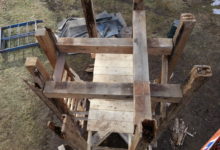
    At East Derry, we knew the lantern was in bad shape, but we couldn’t know the full extent until we had it on the ground. Brian Cox was the job lead. He says, “The will of the church was holding that thing together, many layers of lead paint, and band-aid flashing details.” It was chilling to observe the extent of the damage, and know the structure was in this condition when it was still 80′ above the congregation.

    Lower lantern, inside
    Lower lantern, inside. Photo by author

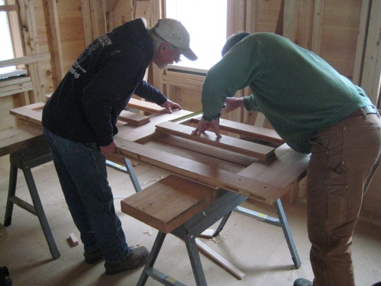
    Once the frame was exposed, we documented and measured every piece. The design is both complex and well-balanced. Each post is connected to its opposite with an upper and lower girt, and a plate across the top. The eight posts hold hands like four couples in a square danceDavid Ewing produced cut drawings for each unique timber. To orient the crew, he provided a key alongside each drawing, highlighting the timber’s location within the frame. This helped the crew organize all the pieces, and to double-check their layout. The color-coded cut key is an innovation we’ll continue to use on all future drawing sets.

    Lantern Posts
    Lantern Posts C1 & B4. Drawing by David Ewing

    The lantern posts are five-sided; when the building is trimmed out, a turned column will adorn each point of the octagon. Four parallel bed timbers cross the belfry plates and support the eight posts. The bed timbers are crossed by a fifth perpendicular timber, which bears the foot of the mast. The plate level is co-planar and arranged like a hashtag. Two full length plates run parallel to the beds, and two interrupted plates run counter to them. The timber hashtag is connected by hefty mortise and tenon joinery.

    Lower Lantern, before. Photo by Arron Sturgis
    Lower Lantern, before. Photo by Arron Sturgis

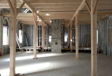
    The lower lantern frame was test fit in our yard in Nottingham, NH. The assembly was smooth and painless thanks to thorough drawings, accurate cutting, and the lull. The doubled, overlapping girts make for a stout frame, capable of enduring high wind-loads at the top of the tower. In dimension, this lantern frame is similar to the one we built to support the Camden spire last year, but the design is very different. Camden was reinforced by an array of braces and had stacked, overlapping plates. The bed timbers there were a stacked hashtag, while the ones here are co-planar and parallel. One of the great joys of this job is seeing the ways in which builders solve the problem of constructing a steeple or spire. The vocabulary of design in a barn is much more consistent; I can accurately model a barn from a phone description. Steeples are not that way, every time I crawl through the hatch, I am greeted by a new, intricate design. Part of our mission, and others, is to protect this repository of proven designs.

    Lantern Fitting. Photo by Brian Cox
    Lantern Fitting. Photo by Brian Cox

    Obviously, there were aspects of the building that did not stand the test of time. The flashing between the upper lantern and the sweep roof was the most significant failure, and the extreme height limited the steeple’s overall maintenance. Brian was determined to minimize the plethora of tiny penetrations produced by face fastening. With every steeple restoration, we run into this conflict: it is much easier to mill and assemble trim elements in the comfort of our shop, allowing us the luxury of heat, and finely maintained cabinet tools. It is possible to work at the church, but then we have to contend with weather, job-site tools, commuting and staging. Brian decided to assemble the eight faces of the lantern in removeable panels that could be reapplied on-site.

    Rusty fasteners indicate where water has penetrated the finish. Photo by Brian Cox
    Rusty fasteners indicate where water has penetrated the finish. Photo by Brian Cox

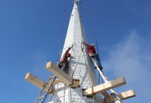
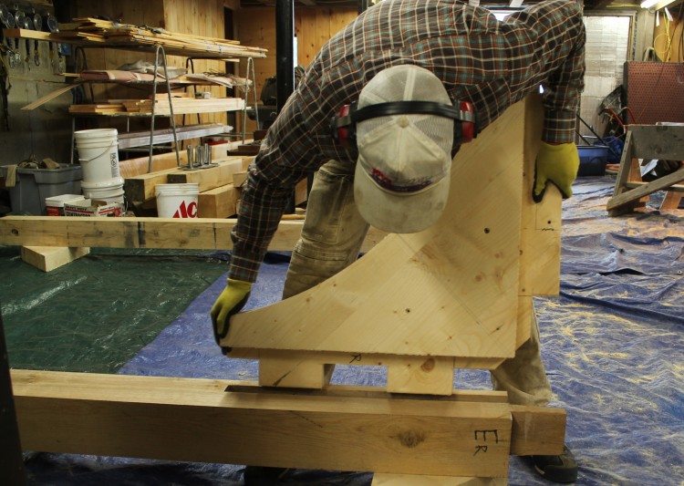
    While the lantern was standing in the yard, the crew fit the sides with horizontal nailers, toe-screwing them to the inside of the frame. They sheathed each face with wide tongue and groove pine, blind-nailing through the tongue. Then they backed out the screws and removed each face as a solid panel. The louvers will be hung on top of the panel – they were never functional – and the panels will be craned in as a unit. This will limit the amount of time the crew has to spend working from a hundred foot staging tower as well as water penetration around the fasteners.

    Flute testing. Photo by Brian Cox
    Flute testing. Photo by Brian Cox

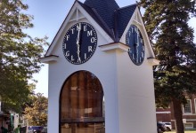
    The frame was decimated, but the most iconic trim details will remain in service. All sixteen urns will be reused, a handful will require new bases. All eight turned columns will be repaired and returned to new, well-flashed pedestals. The louvers and fans will be stripped and re-used, as will the weathervane, and both railings. Cornice trim was painstakingly documented. Sixteen distinct profiles were custom milled by Noah Tremblay and his crew from African Mahogany; the fluted panels and guttae were carved in house.

    Lower lantern and belfry railings. Photo by Brian Cox
    Lower lantern and belfry railings. Photo by Brian Cox

    We’d prefer that these buildings not need our help at all. But given their deteriorated circumstances, we’re grateful we get to do the fix. Next up: scarfing the belfry posts, and joining together the floor, in 12″ x 12″ white oak.


  • Tie Your Spire Down

    Tie Your Spire Down

    Rigging Camden Spire
    Rigging Camden Spire

    Last Thursday, I popped out of bed at 4 am, like Sal on her way to Bucks Harbor. Scott informed me that if I wanted to help remove the Chestnut St Church spire in Camden, I needed to be there by 6:00. By the time I arrived, Scott and Arron had set the rigging. About a third of the way up the spire, eight laminated KD 2x10s poked through the spire like an avocado pit ready to sprout. PTF was hired to direct the spire removal and design a timber-framed transition from the old belfry frame to the new fiberglass spire. We’d worked with the G.C. before on True-Randall farm, Taylor-made Builders are good folks who do high-quality work; so even though fiberglass replacements are not our thing, we got over ourselves because Taylor and his crew are such a pleasure.

    IMG_7233

    This steeple is so tall that a 120′ man-lift couldn’t reach the weathervane on the day we went up there to remove the weathervane (oops). The main church is two full-height stories. Starting just below the main ridge-line, the belfry posts rise 30′ to a plate level just below the clock dials. The original spire rafters penetrate into the belfry, landing on a girt 5′ below the plates. The spire rafters pass through the dial level, behind four 6′ diameter glass dials.  Above the dials, the original spire rafters were severed and sistered with relatively light, laminated 2x4s. That repair was performed in the 1990s by a talented and eager Eagle Scout. This go-round, we designed a timber-framed “lantern” that crosses the belfry plates like a crab. Eight 8×8 posts rest upon the lower crab and support a maintenance floor behind the clock faces. The upper lantern plates, or upper crab, extends well into the fiberglass spire, 6′ above the horizon of the clock faces. Four new fiberglass dial hoods will protect the dials, and be structurally fused to the new fiberglass spire. The lantern frame we’re cutting reproduces the telescoped framing levels found in this building and other historic steeples.

    Lantern Iso, X-Ray
    Lantern Iso, X-Ray

    The model we’d created for the lantern design allowed us to accurately calculate the height at which the rigging would need to be placed in order for the spire to be slightly bottom-heavy as it flew. In fact, once prone in the driveway, the spire balanced like a seesaw on the fulcrum of its rigging. A top-heavy spire might flip mid-air, which would be just as dangerous and scary as it sounds.

    Chestnut St Church, Crane, and Rigging
    Chestnut St Church, Crane, and Rigging

    We hung a cage from the main ball of the frame to protect the weathervane from the rigging straps. We linked together the crane operators’ longest cables and our longest rigging straps, to connect the four corners of the metal frame to our rigging beams. The last strap was doubled over, resulting in an eight point pick.

    Spire cage
    Spire cage

    The crane flew the rigging up to the crew on the top of the staging, and we pulled the rigging straps away from the spire as the operator located the ball directly over the weathervane. The rigging was accessed by ladders off the staging, which was less efficient than it was photogenic.

    Teamwork
    Teamwork

    Once the rigging was securely attached, we crawled inside the spire and used saw-zalls to cut first the spire sheathing, then the mast and then all eight rafters. In my experience, the penultimate step of severing the last connections is the most stressful and variable part of the entire crane day. As Arron warned the crew, a forgotten toe nail could prevent the spire from releasing safely and evenly. We were lucky to have a skillful crane operator from Keeley. We wanted the crane to take enough weight, and put enough tension on the rigging to prevent our sawzall blades from binding, but we did not want the spire to bounce or release with any energy.

    Witch's hat with a crown of thorns
    Witch’s hat with a crown of thorns

    Scott and Arron checked in with the operators. When we started cutting the sheathing, the crane had 1500 lbs of weight on the ball. For the mast, 2500 lbs. As the last of the rafters were cut, the crane was taking 3500 lbs. Unfortunately for the spectators on the ground, a safe spire removal looks slow and boring. Unfortunately for my story, the spire released without any hitches. The spire weighed about 8800lbs, which reflects its light framing.

    A Bittersweet Triumph
    A Bittersweet Triumph

    The crane operator lowered the spire safely to the street, and the crew cut the cone into sections small enough to carted away by a pulp truck. The Penobscot Bay Pilot got some beautifully boring drone footage of the removal, and covered the story, here. For more photos of our process, visit our Flickr album.

    Spire got the drop on you
    Spire got the drop on you
  • The Rosenthorns

    The Rosenthorns

    Clock in Clock Tower
    Clock in Clock Tower

    Over New Years, my intentional friend likes us to sit in a big group and practice “Rose, Thorn and Rosebud.” We say the best thing that happened to us this past year, and the worst, and the thing that we’re looking forward to in the coming year. My rose took so much time that it’s been nearly absent from the blog, but it’s an easy pick: the completion of the Hampton Town Clock Tower. (This is me talking for me, Arron would surely have a harder time choosing. There’s the completion of the first phase of Wood Island, the East Derry undercarriage, Northwood Church and Jennison barn. There’s the installation of the trusses at Troy, and the commencement of undercarriage repairs in Readfield. There’s the long-awaited restoration of the windows in the converted barn that serves as our office, shop and home for Michelle and Arron. Scott Lewis returned to PTF to be our Project Manager, a top contender for blue ribbon). My thorn was losing Joe McAllister to the wilds of Minnesota; I hope his rose was one of projects that he’s since completed out that way.

    Hampton Town Clock Tower stands out because it wasn’t the typical repair fare. Instead of repairing a historic building, we re-interpreted one. In 1990, a catastrophic fire destroyed the Odd Fellows Building in Hampton, NH. The only artifact that could be saved was the Hampton Town Clock, and that had been warped by the intense heat. The clock was given to the town by John T. Brown in 1897, with a dial which spelled out “M E M O R I A L G I F T” in place of numerals so that every person who wonders why it’s half past “G” remembers his generosity. Since 2004, a dedicated group of Hamptonians have been working to restore the clock. They wanted the clockworks itself to be on display, in a housing that referenced its original home.

    Most people think of a clock as a round face with hands and numbers, but a tower clock is the size of a sideboard, with large bronze gears and a 9′ pendulum that swings below it. The round face is called a dial and might be the least interesting part of the whole contraption. Hampton’s clock is a Howard Round top, which means that the gears sit between two half-round carriages, about 4′ wide, 4′ high, and 2′ deep.

    Odd Fellowing Building, photo from Lane Memorial Library
    Odd Fellowing Building, photo from Lane Memorial Library

    The original tower, built in 1895, was too small for the clock, and was raised twelve feet and rebuilt in 1897. The roof was unique, with cross gable pitches topped by a spire reminiscent of a witch’s hat. The roof and dials perched above a belfry with large open arches on each face, and pilasters on each corner.  The committee wanted us to build a standalone clock tower that displayed the clockworks at eye level, referenced the original building, and fit into their budget of just under $100,000. We also learned that the clock would work best if the bell was located beneath it, so that the drive train could be relatively straight, and not be diverted around a large bell. This created our biggest design challenge. We wanted to display the clockworks at eye level, but the clock needed to be located above a bell that stands 5′ high in it’s carriage.

    Tower and staging
    Tower and staging

    At first we designed a building that nearly reproduced the belfry, with its open arches and fluted pilasters. We kept the original gables, but eliminated the witch’s hat. We presented the project at the Crit night of the Portland Society of Architects to get their input on the arrangement of clockworks and bell, and ended up getting better feedback about the roof and trim. They encouraged keeping the original roofline and accentuating the timber frame. We learned from the committee that the pilasters didn’t fit into the budget anyway. Ultimately, we arrived at a design that replicated the iconic roofline, over a much simpler box. We enlarged the arches, which echo the round top of the clock, but lost most of the Victorian trim, which took the focus away from the main object anyways. The timber framed floor hovers just above the bell, and is cut away at either window, so that the view of the clock is obscured as little as possible. The bottom of the clock is directly at eye level, so that visitors look up into its workings. One of the architects dismissed the design as looking like a ticket kiosk, which was OK by us, but I think of it as a building-sized display case for a desk-sized clock. The design process was incredibly rewarding, and the inputs from each stakeholder and committee member improved the design. Together we created a building that better fulfills its purpose than we could have on our own.

    Slated Roof
    Slated Roof

    Lee Hoagland, Jake Imlay and I cut and fit the frame at the shop. The new clocktower would be erected on the front lawn of the Centre School in Hampton, and we needed to complete as much offsite work as possible before we could work onsite during summer vacation. The foundation and site work was donated by Kenny Lessard by the end of the school year, and we erected the frame in early July. With Scott Lewis and Seth Rowell’s help, we sheathed the building and completed the trim. Portland Glass manufactured and installed the 10′ high arch-framed windows, many thanks to Paul Vermette and his crew. Skip Heal of Northeast Lantern donated a reproduction of the elaborate wind directional. The Heritage Company graciously accommodated our tight timeline and slated the eight peaks and eight valleys in August. In November, the clock was installed and running and we celebrated with the community, including many residents who fondly remembered the original tower and the clock’s tolling.

    Hampton Town Clock Tower
    Hampton Town Clock Tow

    While I certainly hope for more new design-build jobs in 2017, my “rosebud” for the coming year is the work we are doing with communities throughout Northern New England to preserve their historic landmarks, and that was the real pleasure of Hampton. We will be collaborating with local contractors in Troy, Readfield and Eastport in the Acworth Model to develop repair plans and share specialized skills. From the committee chair to the on-site carpenter, we are fortunate to work with folks who really care about their neighbors. We work with people who donate a lot of time, knowledge and money to a communal cause: saving the structures that serve as a reminder of our shared history and as meeting places that knit the community together.

    Hampton Town Clock Committee
    Hampton Town Clock Committee

  • After Fire, a Family Doubles Down on Preservation

    After Fire, a Family Doubles Down on Preservation

    Restoring an historic building takes a lot of stamina. The sense of warmth and meaning one feels within a restored structure comes from the labor invested by the craftspeople who built it and the experiences of the community that used it. Once complete, the Steiner-Truesdale residence in Newfields, N.H.,will reflect not only a century of life as a church, but also the owners’ dedication to restore it as a family home, twice. In April, a fire destroyed much of the interior, an 8-year long labor of love for owners Jack Steiner and Kimberly Truesdale. In November, PTF began its role in the home’s re-restoration.

    Ribs and Roof system
    Ribs and Roof system. Photos by Brian Cox

    Newfields’ Sacred Heart Church was built in the 1880’s — a transition frame, 40′ wide by 80′ long. Five interior timber bents were constructed from a pair of posts, a pair of steeply pitched rafters, two pairs of ribs and a collar tie. The lower ribs brace the posts to the rafters and the upper ribs brace the rafters to the collar tie. The ribs are let-in and bolted, rather than mortise-and-tenoned, reflecting the dominant technology of the period. A tie rod takes the place of a tie beam, tying the eave walls together. Had the church had been built in stone, in the original Gothic style, buttresses would have provided the support necessary to counter the outward thrust of the rafters. The roof system is substantial, consisting of the principal rafters let in with principal purlins and infilled with common rafters. The balloon studs run from sill to plate, and are spaced approximately 20 inches on center. The plate consists of doubled 2x stock, which is mortised and fit onto a tenon at the top of each of the posts.

    Stopped chamfer detail
    Stopped chamfer detail

    PTF was hired to rebuild a second floor that had been destroyed in the fire. The height of the floor was determined by the tie rods, so that the rods could be enclosed between the 10″ high floor joists. Two 8″ x 10″ x 60′ floor girts run parallel to the eaves, supporting the joists. Five pairs of posts, in line with the bents, support the girts. The posts rest on first-floor girts, or carrying timbers, parallel to the girts above. The carrying timbers rest on masonry piers set directly beneath the posts, point-loading the interior structure to ground. Ultimately, the entire frame will be exhibited within the living space. The timbers were planed, and the crew matched a chamfer detail from work that Jack completed: a 1″ chamfer on all posts and girts, a 5/8″ chamfer on joists and braces, stopped 1 1/2″ from joinery.

    Once onsite, Brian and the crew’s first step was to unload and organize the stock. In addition to the six 8″ x 10″ x 20+” stock required to create the second floor girts, there were more than seventy-five 4″ x 10″ x 12′ joists, ten posts, and sixteen white oak braces. The crew, Brian, Shawn and Seth, took half a day to lug lumber, moving the timbers along a pick through the window, and another day just to organize it all. Organizing timbers is like sharpening chisels –t ain’t romantic, but it’s necessary to a well-run job. A clean and well-organized job site makes a big difference in the efficiency and accuracy of the good stuff, such as cutting joinery.

    Shawn, girt timbers, and Shawn's breath
    Shawn, girt timbers, and Shawn’s breath

    All the joinery was cut and test-fit on sawhorses prior to installation. Each 60′ second floor girt was made up of three 20+’ sticks joined with two bladed scarf joints. Cutting a frame indoors in November sounds like a pretty cushy job, but because the floor girts and joists were so long and still green, the crew wanted to do everything possible to prevent them from corkscrewing, and this meant working without heat. With the heat off, the timbers would dry more slowly, ensuring their stability. Furniture makers will sometimes avoid kiln-dried wood, instead stacking freshly-cut boards evenly; plenty of air flow lets the boards dry naturally over the course of years.

    Thanks, Grandma! the scarf fits perfectly.
    Thanks, Grandma! the scarf fits perfectly.

    Each of the posts was connected to the floor girt by two braces. After cutting, all of the brace joinery, as well as the six scarves, were fit and laid out on sawhorses. In order to prevent the joinery from opening as the timbers dried, the crew decided to draw-bore all the joinery. Draw-boring is a joinery technique in which the pin hole in the tenon is placed 1/8″ closer to the shoulder of the joint than the pin hole in the mortised piece. A tapered pin is driven through the holes, squeezing the mortise and tenoned pieces closer together.

    Lee and Scott assist with assembly
    Lee and Scott assist with assembly

    After the pinholes were drilled, the crew erected two towers of staging along the center of the church. Using a chain fall, they lifted the three pieces of one girt into place, and re-assembled and pinned the girt on the staging. Next, they righted the posts and threaded their feet through holes in the first floor, maneuvering the posts into mortises on the carrying timbers below. Due to variation in floor depth, the posts were buried 9 1/2″ – 22″ below the surface of the first floor. The crew squared and plumbed the posts and temporarily braced them to the exterior walls with 2x lumber. Then the oak braces were fit into their mortises and pinned.

    Second floor girt in position, and blurry
    Second floor girt in position, and blurry

    Three one-ton chain hoists were needed to raise the assembled 50′ floor girt into position, 4 1/2″ above the post shoulders (and 1/2″ above the ends of the tenons). The girt just kissed the 1″ round tie rods, which ultimately run between the 10″ high floor joists. When the weight was released from the staging ledgers, those ledgers sprung up, and as the ledgers were removed, their wedges popped out with a “ping.” Coordinating efforts, the crew released the chain falls and slowly lowered the girt onto the five post and eight brace tenons. Then they pinned the joinery. For the second girt: rinse, and repeat.

    Floor framing, resurrected
    Floor framing, header visible near window, far left

    The second floor is supported by more than seventy-five 4″ x 10″ x 12′ joists, which were lifted into place using a winch. At each of the eight windows, the crew created a window well by inserting a 6″ x 10″ header between the joists adjacent to the window, so the top of the window and the arched trim can be seen from the first floor. The header fit into a pocket into the adjacent full-length joists, and the short joist sits in a pocket in the header.

    With the framing now complete, the Steiner-Truesdale family can finish their adaptive re-use of this Gothic Revival beauty. We were truly saddened to hear of the fire, and now we are honored to be part of this building’s journey.

    Completed framing, from below
    Floor framing, from below

  • Guest Post by David Ewing: iFarm update

    Guest Post by David Ewing: iFarm update

    Tom and Dan, assembling a frame and panel door, photos by Dave Ewing
    Tom and Dan, fitting the center stile of a frame and panel door.  Photos courtesy of the author

    Since 2009, the iFarm in Boxford, Massachusetts has been keeping crews from PTF busy. Christine Barensfeld, the owner of the farm, has collaborated with PTF to restore the farm which consistently operated from 1750 – 1932.  Chris purchased the farm in 2009 a midst the threat of developers who would have purchased the property and parcelled the land for the construction of new homes.  Since then, Chris has been accruing as much information as possible about the farm’s history, originally known as Towne Farm.  She has held several events at the farm providing lectures, slides shows of historic photographs, exhibits of archaeological artifacts found on the farm, and tours of the property.

    iFarmhouse, 2013
    iFarmhouse, 2013

    Chris’ concept to restore the farm covers both architectural restoration as well as re-establishing 19th-century agricultural operations.  She has composed a team of professionals who have been collaborating to help her reach this goal.  Preservation Timber Framing is proud to be a part of this unique team which includes Benjamin Nutter Architects, Howell Custom Building, Landscapes by Lillabeth.

    When I arrived to iFarm in August of 2012, efforts to restore the farm had been well underway. The projects that had been completed included the restoration of the barn, carriage house, utility shed, and water tower.  Focus during the early fall of 2012 was directed to the construction of a timber framed kitchen-ell addition to the original late-18th century farm house.  The frame was raised just before thanksgiving in November of 2012.

    Repaired second floor system
    Repaired second floor system

    Since that time we have been concentrating on the marriage between the old and new through the restoration of interior structural and finish components.  This has included tandem maneuvers re-leveling floors systems while selectively replacing deteriorated floor joists and a severely rotted beam which supported the chimney hearth.  Work has also been done to slightly reconfigure the room layouts in an effort to reestablish the original late 18th century design.

    Casing detail
    Casing detail

    Along the same thread of re-establishing the original design Dan, Keith, and Tom have used their combined expertise to determine what interior casing details are original to the construction of the house.  In the north-west bathroom we found the original interior casing of the window to be simple, with a single bead on the corner.  This discovery matches the single beaded baseboard and post casings in rooms on the second floor.  Using this information we have embarked on repairing existing casing and replicating this detail by custom milling identical 3/4 and 1 inch pine casing for the doors, windows, structural frame, and as baseboard.

    Door, partially assembled
    Door, partially assembled

    Additionally we have fully restored all of the doors original to the house, as well as doors for the addition that Chris and Benjamin Nutter Architects bought from a local architectural salvage yard.   The steam box method of scraping large quantities of doors, windows, etc. has proven to be the most effective and non-toxic method of removing lead paint.

    As work is steadily heading in the direction toward a full restoration of the farmhouse, complete with a new historically compatible kitchen-ell, there is never a dull moment on the farm.  Most recently in a collaborative effort with Lillabeth, Chris has recruited us to construct six 30’ tall bamboo teepees. The teepees will be used as a trellis to aid in the growth of hops.  Taking approximately three years to harvest the hops, Chris will be starting her nano-brewery this summer.  Any ideas on a name for this sure-to-be-tasty brew?  I, for one, like the name Towne Road Beer!

    The author, installing window casing
    The author, installing window casing

    More on iFarm here.

    David Ewing came to PTF through the Maine Preservation intern program.  While working at PTF, he is pursuing a degree from Boston Architectural College.  David lives in Dover, NH with his wife and beagle.

  • New Castle Gaze Bo

    New Castle Gaze Bo

    In the shop, Seth fitting brace tenons
    In the shop, Seth fitting brace tenons

    Preservation in the field can take many forms.  Most of the time, preservation is the most practical and reliable answer to a client’s needs, but there are times when pure preservation isn’t feasible, or reasonable (see Demeritt-O’Kane).  The New Castle Congregational Church and gazebo offers an alternate model.  The congregation has endeavored to preserve the main body of the church, repairing the undercarriage framing, and rebuilding the foundation under the rear additions of the building.  When it came time to repair the dome topping the steeple, however, the building committee was faced with a proposal: if they allowed a cell tower to be built on top of the tower box, the cell company would pay for a new dome, in addition to monthly rent during the long-term lease.  When the congregation chose to lease the space to the cell company, the dome was replaced with a hollow, fiberglass replicate.

    Additionally, the cell company contributed to funds raised by community members for the complete restoration of the original dome.  Some of the money from the cell tower helped to pay for a custom gazebo to support the restored dome.  Its historical integrity was compromised, but at least the dome would be put to use.

    The design process was a challenge.  The building committee wanted a gazebo space that was large enough for weddings and other functions, but the original footprint of the belfry wasn’t big enough.  From a design perspective, the gazebo needed to echo the original tower trim, but not overpower it.  Due to distance and perspective, steeple cornice trim can be comically large when viewed up close; it is one of the most persistent surprises since I’ve started doing this work.  Given these restrictions, Ed and Keith designed a gazebo that honored the original craftsmanship of the dome, without distracting from the classic composition of the church.

    Frame design, shop drawings
    Frame design, shop drawings

    The preservation of the dome was completed first.  The huge, curved rafters reproduced using a Prazi beam cutter, which is a chainsaw bar and chain attached to a circular saw in place of the saw blade.  The Prazi functions like a jigsaw on steroids.  Other elements of the original framing were retained, like the struts that run diagonally from plate to mast.The gazebo’s timber frame design was ingenious.  The eight-sided structure consisted of four main bents and four diagonal plates, which overlapped and connected the main bents.

    Keith using drawknife to smooth curved brace
    Keith using drawknife to smooth curved brace

    The curved braces were cut from a solid, 3″ thick glue-up.  The curve was roughed out by the Prazi, and smoothed with a combination of drawknife, spokeshave, and sander.

    Bent Stack
    Bent Stack

    The main bents were assembled in the shop, their joints were pinned, and then stacked neatly.  They were loaded onto the trailer and driven to New Castle, where we were met by a crane.  The crane unloaded each bent from the trailer and stood the frame onto its feet already located on an octagonal concrete pad.

    Placing Bents
    Placing Bents

    As the bents were unloaded, they were braced temporarily, and capped with their respective plates, creating the alternate four faces.  Working against the crane operator’s clock, we carefully laid sleepers across the plates and tapped them into their final resting places.  Once the sleepers were placed, the crane lifted the cherry-colored dome and placed it on top.

    Tarp-tented gaze-bo
    Tarp-tented gaze-bo

    The weather in the weeks that followed started with a heat wave and finished with a week-long downpour.  When the weather threatened to derail and July 4th deadline, we opted to drape the entire structure in an improvised tarp tent.

    Cornice detail
    Cornice detail

    Under the tent, we were able to complete the cedar shingling of the skirt roof, hanging the cornice, casing the posts and braces and hanging beadboard on the ceiling.  Our friend Iain Mackenzie turned and installed a custom balustrade.  By July fourth, the tarp was removed, and New Castle was able to dedicate the gazebo on Independence Day.

    Gazebo, completed (unpainted)
    Gazebo, completed (unpainted)

    New Castle’s approach may not fit the preservation ideal, but it was a compromise that ultimately led to a new community space and the adaptive re-use of a significant architectural artifact.  See more photos in our Flickr set.

  • A Marriage of Traditional Joinery and Modern Engineering

    Dan, harder at work

    On Wednesday, the crew down at iFarm raised a new timber-framed kitchen ell.  The modified English frame is based closely on joinery found in the late-18th century house.  We based the size and location of the addition on evidence found in the house frame of an original, and now demolished, ell.  Like the house frame, the reproduction ell is constructed of White Oak and Eastern White Pine, in addition to Spruce, a species dictated by engineering requirements.  We worked with structural engineer Joe Fix, and architect Ben Nutter, as well as Howell Custom Builders, to build an historically accurate, traditionally-joined frame that met all Massachusetts building codes and regulations.  Click on the slideshow below for more information:

  • O’Kane Notebook II: Post-colonial Builder Stoked on Sweet, New Plane

    Crown Above Fireplace in Blue Bedroom

    Over the past week, we have been using up our supply of softwood wedges at the O’Kane House.  In the effort to gently remove the delicate, hand-planed moldings, we tap narrow wedges in along the paint lines, crushing the wedges with repeated use (and saving the edges of the trim).  It is a slow, thoughtful process and along the way, we speculate about what the original carpenters of 1790 might have been thinking.

    There is strong evidence that the trim carpenter who finished the front hall and the upstairs bedrooms was thinking, “OMG, Can’t get enuf of this sweet, new reeding plane!”  The pattern of five 3/16 inch half round “reeds” is used to create a variety of decorations around the room.  So far, all of this molding has been hung with wrought nails.  The accordian lath behind it was hung with a combination of cut and wrought nails.  This was typical for the time period, according to A Building History of Northern New England, by James Garvin.  Cut nails broke more, but were less expensive to make, so a few wrought nails were used to hold the lath in place, and then the field was filled in with cut nails.  It makes sense to me that the carpenter wouldn’t risk breaking a cut nail as he hung his precious, hand-milled moldings.  It was worth it to stick with the more trusted technology, the wrought nail.

    Echinus Molding in Front Hall

    He used it in multiple runs adjacent one another to adorn the echinus of the pilasters next to the front door.

    Fireplace Surround, Blue Bedroom

    And he ran multiple passes on one 6 or 7 inch board that he then cut on the diagonal and reassembled to dress up the simple fireplace surround.

    Reeding Plane Runs into Knot

    We get sort of excited when we see mistakes like this one.  When we turned the board over, we saw the knot that caused the plane to go off-track.  I like to imagine commiserating with the post-colonial carpenter around the horse trough.  It’s evidence like this that will remind the client that he lives in a wholly handmade house.  There are some moldings that we may have to reproduce, and for short sections, it is easier to do by hand. If anyone out there has seen a plane like this one, please let us know.

    For more photos on the process, check out the photos below, updated regularly with our daily finds.

  • Yours Gluely

    Hill Fireplace
    Hill Fireplace

    The Hill fireplace is nearing completion.  From the outset, this project has been among our most rewarding.   We designed the panelled wall using HABS drawings from a house built by the father of the builder of this house.  Knowing that the design is grounded in historical precedent lends the project a sense of purpose greater than that of simply filling in the space around a fireplace.

    Fireplace Return Panel
    Fireplace Return Panel

    The paneled wall is composed of three frames, joined by mortise and tenon.  One, that surrounds the fireplace opening itself, contains a large panel approximately 3′ x 6′.  Its 8′ stiles extend past the panel to the floor, and the joint between the flat panel and the stile is covered by a bolection molding developed from the John Cram HABS drawings.  The same bolection molding will cover the joint between the lower half of the stile and the masonry.

    Adjacent the right side of the large panel is an open frame that will enclose a bookshelf, and perpendicular to the left edge is a third frame with a panel in its lower half, and a bookshelf above.

    Pilaster Layout Close Up
    Pilaster Layout Close Up

    The front wall plane will be adorned with three pilasters, designed from the Cram drawings, which handily obscure the joint between the two front frames, and their edges.  The pilasters are not only decorative, as their obfuscation allows the front frames an expansion joint, that will move with the weather.


    When I first approached this job, I was sure that the many mortise and tenon joints would pose the greatest challenge.  And while they were a lot of fun, they came together with relative ease, and the glue ups were the most interesting aspect of the first phase of the process.  Years ago, I used to wonder whether there was a word for glue-up phobias, because I clearly had it.  The idea of the glue dripping and drying as I scrambled to fit the swelled joinery once filled me with dread, but over time I’ve borrowed tips here and there to develop a stress-free system that results in remarkably flat panels.

    The larger of the two panels was 6′ x 3′.  Historically, a plane of this size would have been broken up by a stile or rail to accomodate panels composed of single boards, some of which were over 2′ in width.  However, the client has a specific painting that she wants to hang over the fireplace, and we thought it an appropriate compromise to create the panel by gluing together four boards.  We’ve seen wide glued up panels in houses of a similar age, such as in the O’Kane House, in Durham, NH.

    Half Glue Up
    Half Glue Up

    The biggest challenge when gluing together a wide panel is keep the whole assemblage flat. My contemporaries would recommending gluing together narrower pieces to keep it stable, but we wanted to use wider boards to better approximate the panel that may have originally been; so we used four,  9 1/2″ wide, eastern white pine boards.  Tom and I started by jointing a face (flattening the face on a jointer), and then running the board through the thickness planer to create a parallel face, and then jointing an edge, and using our new SawStop to create a parallel edge.  I then laid the boards out with their best faces up, arranging and rearranging to achieve the tightest joints and flattest initial surface.  I then drew marriage marks across each of the joints, and used the marks to reference the biscuit jointer.  A biscuit jointer adds to the prep time for glue ups, but I think that it has been the most important changes in my path towards glue-up enlightenment.  After the glue is applied, no longer do the boards twist and slide past one another like Jamiroquai and his couch in the Virtual Insanity video.  As the pipe clamp is tightened, the biscuits help to hold unruly boards to their better behaved brothers.  They allow you more time to arrange your pipe clamps and cauls.

    Panel, half scraped, see its shine?
    Panel, half scraped, see its shine?

    I glued the panels in two pairs, and then glued the pairs together.  I then used a cabinet scraper to remove some of the larger globs that had squeezed from the joint, and followed it with a random orbital sander.  I tend to be snobby about sandpaper, thinking it a lesser method of smoothing and flattening, but for taking down the glue between joints (if it has hardened too long) I have found nothing better.  Sandpaper abrades the surface of the wood, always leaving a slightly fuzzy surface, while planes and cabinet scrapers cut the fibers, leaving a smoother, shiny surface.  In most cases, a plane is also faster.  But I couldn’t risk the tear out that might occur if the flat-sawn boards had adjacent grains that run in the opposite direction.  I was still able to achieve a traditional finish by following the sander with a cabinet scraper and extremely sharp block plane.

    Raising Panel
    Raising Panel

    After the panel was smoothed, I relieved the backside, creating a raised panel.  Because the client wanted a flat panel on which to hang her painting, the work will never be seen, but like a lot of traditional forms, the fielding serves a purpose.  It relieves the edge so that it will fit in a dado (groove) that runs in the edge of the stiles and rails, but allows the center of the panel to remain at a full 3/4 inch thickness, which increases its stability.

    I transported the frames and panels to Hampton Falls, where they were assembled, and pinned.  Tom and I spent the last week installing the frames, and adding the pilasters and trim.  Please peruse the installation photos below, and check back for final shots of the completed work.

  • HABS to Watch Out For

    Hill Fireplace
    Hill Fireplace

    Tomorrow we embark on the building of the Hill fireplace.  The Hill house is a turn of the 19th century farmhouse, with all the attendant revisions and additions.  The owner wants to restore her fireplace to reflect the time period it was built and the building trends in her region.

    Through her own research, she believes the original building may have been constructed by John Cram, a prolific local builder.  Fortunately, the John Cram farmstead, also in Hampton Falls, NH, was documented by the Historic American Building Survey, and was available through its database online.  The Historic American buildings Survey was a program of the National Parks Service, that was developed in 1933 to provide work for architects, draftsmen and photographers left jobless by the Great Depression.  Not only are the drawings and photos an incredible resource for our work, browsing through them leaves one with an incredible sense of patriotism.  They document the best work of craftsmen throughout America, and are evidence with our abiding connection with history.  Not only that, but one happens upon some pretty great photography.

    John Cram Fireplace
    John Cram Fireplace

    So, the John Cram Farmstead.  Out of the three documented fireplaces, the design above best fit the bare hearth that we are working with.  We experimented in SketchUp with a number of pilaster designs.  The others were faithful to classical elements and proportion, with a proper capital, and entablature.  We kept coming back to this John Cram design, however, with its unorthodox use of crown incorporated into the capital.  Though purists might reject it, the John Cram pilaster is simpler, and more appropriate to a vernacular building.  This pilaster may not have been found in Greece, but it was found here, in Hampton Falls, NH.  It makes sense, given the house’s location and style, but more importantly, because of HABS, we have good evidence that this was what was built in this area at that time.

    Hill Molding Profiles, from Cram
    Hill Molding Profiles, from Cram

    The John Cram HABS drawings also gave us detailed molding profiles.  Using a Williams and Hussey molder shaper, we will mill custom crown, bolection, and bed moldings based on the HABS details.  The client wanted to make one significant change to the John Cram style, instead of the raised panels, she wanted flat panels with a bolection molding, which would accommodate a painting to be hung above the fireplace.  In A Building History of Northern New England, by James Garvin (pg 137), we found a bolection molding that was identical to the astragal found at the top of the John Cram pilaster.  The only difference is in the millling of a rabbet on the back of the bolection molding stock. Utilizing HABS, we were able to design a fireplace surround that not only fits the house’s age and vernacular style, but adjusts to the needs of its contemporary homeowner.

    Tomorrow, we will lay out the framing around the hearth.  Dave and Brian will prepare a plumb and level wall, while Tom and I will mill the stock, and cut and fit the joinery back at the shop.  I can’t wait to get started on the frame and panels, but I’ll pause to post about our progress along the way.

Think we can help? Get in touch.