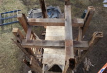
At East Derry, we knew the lantern was in bad shape, but we couldn’t know the full extent until we had it on the ground. Brian Cox was the job lead. He says, “The will of the church was holding that thing together, many layers of lead paint, and band-aid flashing details.” It was chilling to observe the extent of the damage, and know the structure was in this condition when it was still 80′ above the congregation.
Lower lantern, inside. Photo by author
Once the frame was exposed, we documented and measured every piece. The design is both complex and well-balanced. Each post is connected to its opposite with an upper and lower girt, and a plate across the top. The eight posts hold hands like four couples in a square dance. David Ewing produced cut drawings for each unique timber. To orient the crew, he provided a key alongside each drawing, highlighting the timber’s location within the frame. This helped the crew organize all the pieces, and to double-check their layout. The color-coded cut key is an innovation we’ll continue to use on all future drawing sets.
Lantern Posts C1 & B4. Drawing by David Ewing
The lantern posts are five-sided; when the building is trimmed out, a turned column will adorn each point of the octagon. Four parallel bed timbers cross the belfry plates and support the eight posts. The bed timbers are crossed by a fifth perpendicular timber, which bears the foot of the mast. The plate level is co-planar and arranged like a hashtag. Two full length plates run parallel to the beds, and two interrupted plates run counter to them. The timber hashtag is connected by hefty mortise and tenon joinery.
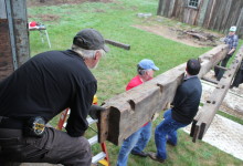
Lower Lantern, before. Photo by Arron Sturgis
The lower lantern frame was test fit in our yard in Nottingham, NH. The assembly was smooth and painless thanks to thorough drawings, accurate cutting, and the lull. The doubled, overlapping girts make for a stout frame, capable of enduring high wind-loads at the top of the tower. In dimension, this lantern frame is similar to the one we built to support the Camden spire last year, but the design is very different. Camden was reinforced by an array of braces and had stacked, overlapping plates. The bed timbers there were a stacked hashtag, while the ones here are co-planar and parallel. One of the great joys of this job is seeing the ways in which builders solve the problem of constructing a steeple or spire. The vocabulary of design in a barn is much more consistent; I can accurately model a barn from a phone description. Steeples are not that way, every time I crawl through the hatch, I am greeted by a new, intricate design. Part of our mission, and others, is to protect this repository of proven designs.
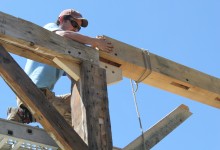
Lantern Fitting. Photo by Brian Cox
Obviously, there were aspects of the building that did not stand the test of time. The flashing between the upper lantern and the sweep roof was the most significant failure, and the extreme height limited the steeple’s overall maintenance. Brian was determined to minimize the plethora of tiny penetrations produced by face fastening. With every steeple restoration, we run into this conflict: it is much easier to mill and assemble trim elements in the comfort of our shop, allowing us the luxury of heat, and finely maintained cabinet tools. It is possible to work at the church, but then we have to contend with weather, job-site tools, commuting and staging. Brian decided to assemble the eight faces of the lantern in removeable panels that could be reapplied on-site.
Rusty fasteners indicate where water has penetrated the finish. Photo by Brian Cox
While the lantern was standing in the yard, the crew fit the sides with horizontal nailers, toe-screwing them to the inside of the frame. They sheathed each face with wide tongue and groove pine, blind-nailing through the tongue. Then they backed out the screws and removed each face as a solid panel. The louvers will be hung on top of the panel – they were never functional – and the panels will be craned in as a unit. This will limit the amount of time the crew has to spend working from a hundred foot staging tower as well as water penetration around the fasteners.
Flute testing. Photo by Brian Cox
The frame was decimated, but the most iconic trim details will remain in service. All sixteen urns will be reused, a handful will require new bases. All eight turned columns will be repaired and returned to new, well-flashed pedestals. The louvers and fans will be stripped and re-used, as will the weathervane, and both railings. Cornice trim was painstakingly documented. Sixteen distinct profiles were custom milled by Noah Tremblay and his crew from African Mahogany; the fluted panels and guttae were carved in house.
Lower lantern and belfry railings. Photo by Brian Cox
We’d prefer that these buildings not need our help at all. But given their deteriorated circumstances, we’re grateful we get to do the fix. Next up: scarfing the belfry posts, and joining together the floor, in 12″ x 12″ white oak.
An enduring feature of timber frames is that they can be dismantled and re-used. A traditional barn-raising, in which a community comes together to erect a frame in one day is preceded by weeks of joiners’ labor: cutting and fitting the posts, girts and braces, plates and tie beams. With the help of many hands, or a gin pole, or a crane, a frame can be raised or dismantled in a day. The relative ease of assembly, and more importantly, disassembly, is why we sometimes find 300 year old frames in 200 year old buildings. The act of preservation and adaptive re-use is a centuries-old tradition, regardless of the age of the frame itself.
This year, engaging in this tradition has been equal parts fun and maddening. We were hired to decipher two frames tagged and disassembled by other contractors. One was the Reverend Morrison House, c. 1726, which was considered to be the oldest house in Londonderry, NH, and is being restored by the Londonderry Historical Society. The other is the French House, c. 1804, a 2-story hip-roofed house that was slated for demolition in Kingston, NH. It’s being restored by Charley and Sheila Foley, who are becoming old hands at this. Both frames were tagged before dismantling, but neither is attended by a full set of tagging drawings. We use tagging drawings like the picture on the box of a jigsaw puzzle. While we try to follow consistent tagging patterns, tagging a frame is pretty idiosyncratic. It’s unlikely that any two PTF frames would have tagging consistent enough to decipher the tags without drawings. That’s what made deciphering these frames such a…fun-show.
SST7 and its old friend, Tom
The Rev. Morrison House was dismantled with tags similar to our own. Alphanumeric codes identified the location of the piece, the type of framing member, and its number in a sequence. We could tell, based on timber size, and the half dovetail at its end, that SST1-SST7 were tie beams. But was SST1 at the outside wall of the west ell, at the west gable, or at the east gable? And what did SS mean? That one remains a mystery.
South eave, prior to dismantling. Photo courtesy Londonderry Historical Society
Although a disassembled frame looks a little like a giant’s game of pickup sticks, it’s actually pretty easy to decipher how each timber was used. The joinery at either end of a timber communicates whether it was vertical or horizontal, and the joinery along its length tells us a lot about it’s location.
Knowing the English tying joint allows us to identify the timbers that establish the overall dimensions of the building. This joint is where the post, plate, tie beam and rafter intersect. The plate is a timber that runs parallel to the eave at the cornice and passes over the exterior half of the eave wall posts. The tie beam crosses the plate, directly over a post and directly beneath a principal rafter. Tie beams prevent the eave walls from spreading under the outward thrust of the rafters. The end of the tie beam is cut into a half dovetail, and performs a mechanical task that contemporary builders assign to metal fasteners. More about tying here, and here. The plate accepts the tie in a half-dovetail-shaped mortise. In order to secure all this framing, the post is joined to both plate and tie. It is flared at the top, sometimes in an iconic, stepped “Gunstock” shape. The interior half of the post extends vertically past the plate and terminates in a “teasel” tenon, which inserts into a mortise in the tie beam.
Tie beam end with half-dovetail and rafter mortise
We could identify tie beams by the half dovetails at either end, their size, 11″ x 11″ x 20′, and the long rafter mortise located right over the dovetail. The joinery in between will tell us whether the tie beam was located on either end of the building or across the middle. Tie Beams are located above the posts at the level of the attic floor. A tie beam from the gable end will have open cog mortises to receive attic joists along its top and interior faces. It will have closed stud mortises along its top and bottom faces towards its exterior, reference face. The reference face will most likely have a series of fastener holes left over from the sheathing. A tie beam from the middle of the building will look different. It will have cogs for attic joists along both sides. It will not have stud mortises on its top face, and it may or may not have stud mortises along the bottom, for partition walls. It was easy to tell the EPlate1 and WPlate1 were gable tie beams and the TS1 and TS2 were the interior ties. The carpenter who dismantled the building apparently considers all major beams that ring the post tops “plates” and, you know, that’s his prerogative. I guess he didn’t read this.
Tie beam end in plate pocket
Plates, as we define them, run along the eave across the tops of the posts. In older timber frames like the Rev. Morrison house, they are smaller than tie beams in section, 6″ x 11″, but longer: 30′. The Reverend Morrison House has a long shed off its north wall and a shed off its west wall, too. The north shed plate was much smaller, 5 1/2″ x 9″, but 46′ long. This little plate received the short ties SST1-SST6 in an evenly spaced series of dovetail mortises. A plate will have post mortises and stud mortises along its bottom face. In18th and early 19th century timber frames, “English” timber frames, the plates will be the longest continuous framing members.
Gunstock post tops. Plate tenon on top, teasel below
In an “English” frame, the post will be the easiest timber to identify. The Morrison house had beautifully stepped gunstock posts, 14′ 3′ long, 7 1/2″ x 9″ at the bottom and 8″ x 12 1/2″ at the top. The plate and teasel shoulders are offset from one another by two to four inches and the end tenons are oriented 90 degrees to one another. A corner post will have brace and girt mortises along two outside faces. Interior eave posts will have brace and girt mortises on opposite faces, and in a two-story building like Morrison, a second floor girt mortise on its interior face. The orientation of the stub tenon on the bottom of the corner posts will indicate how the original perimeter sills were arranged.
Perimeter girts will contain joist pockets that reveal joist orientation and joist layout. The Rev. Morrison house had an enormous chimney girt, 9″ x 14 1/2″ x 18′ 8 1/4″, and second story summer beam that connected the chimney girt and the east gable end girt, 10″ deep by 16″ across.
Saltbox west gable. Image courtesy Londonderry Historical Society
Once the timbers were identified, we were able to arrange the second and attic floors on the foundation that had been poured before the untimely death of one of the project coordinators. Just when the pieces were starting to fit together, the real mystery of this house was revealed. At the time of its dismantling, the building was a traditional saltbox shape. There were three bays, 12′, 8′ and 20′ wide, measured from reference to reference, west to east. We were told that the West bay (12′ wide) was a later addition, and the plates confirmed this.
West end of plate, upside-down
The ends of the plates were totally weird. They terminated in a sloped, stepped shoulder that we’d never before seen in so many years of investigating scarf joints. The end of the plate was long incline, that was sliced to half its width, as in a sloped, vertical lap joint. But the shape of the joinery wasn’t the weirdest thing about the plate. The weird thing was that it extended past the second bent, past the second pair of posts, by about sixteen inches. While the ends of some tie beams extend past the eave walls to create an overhang, that is a later style that was clearly not the case in this building. The overhang is not mirrored on the opposite gable end, and the ties do not overhang the eave walls. The building could not have originally ended at the current second bent, because there would have been two oddly shaped plate ends poking out of the west gable end of the building.
West end of plate, with extension in place
But the length of the plates remained a curiosity, why did they extend west, past the outside faces of the posts? Additionally, the west gable wall posts were not continuous like the posts in the rest of the building. Ultimately, we determined that there were a pair of short teaseled posts on the first floor, with their teasels facing east, towards the main building. Originally, these posts were topped with a tie beam at the second story level, running perpendicular to the gable. Later, the tie beam became a second floor girt. A second pair of posts were cut and stacked atop the first, their teasels facing one another and linked with a tie beam parallel to those in the rest of the building. A single story ell preceded the saltbox roof on the west bay. Photos from the dismantling revealed that the chimney, located in the center, 8′ bay, was built with three fireplace openings, facing East, North and West. The fireplace opening and plate length indicate that a west-end, shed-roofed ell was original to the structure. The weird sloped shoulder cut into the end of the plate originally received shed rafters.
Tie beams, early and late. Later tie beam “WPlate” is up top
Investigating the tie beams confirmed our suspicions. When the building was dismantled, the tie beam on the west gable end was labelled “WPlate.” The next tie beam in was labelled TB1. TB1 served as the west gable tie beam when the building was built around 1726. Above, WPlate and TB2, a mid-span tie beam, lay next to one another. You can see attic joist pockets in TB2, and that they are laid out evenly until they get to the chimney mass, where there is a gap in the sequence. Both tie beams are hewn, but the hewing in the upper timber is more crude, and consistent with the quality of hewing on the plate extensions. The hewing in the rest of the frame was consistent with the fine hewing of the lower timber. The later timber is still quite early, and contains a number of wrought nails. This indicates that the west bay was converted from shed roof to salt box in the first quarter of the 19th century, at the latest.
Morrison House Isos
It took us nearly a week to extract the timbers from the trailers, decipher their use and document their dimensions. We used that information, along with dismantling photographs, to create a scale 3D model in SketchUp. Using this information, the Londonderry Historical Society can restore the building, and decide the time period to which they will interpret. Ultimately, deciphering a dismantled frame is like a Times crossword puzzle, the degree of difficulty is matched by the feeling of pride and satisfaction in the solution.
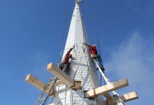
Last Thursday, I popped out of bed at 4 am, like Sal on her way to Bucks Harbor. Scott informed me that if I wanted to help remove the Chestnut St Church spire in Camden, I needed to be there by 6:00. By the time I arrived, Scott and Arron had set the rigging. About a third of the way up the spire, eight laminated KD 2x10s poked through the spire like an avocado pit ready to sprout. PTF was hired to direct the spire removal and design a timber-framed transition from the old belfry frame to the new fiberglass spire. We’d worked with the G.C. before on True-Randall farm, Taylor-made Builders are good folks who do high-quality work; so even though fiberglass replacements are not our thing, we got over ourselves because Taylor and his crew are such a pleasure.
This steeple is so tall that a 120′ man-lift couldn’t reach the weathervane on the day we went up there to remove the weathervane (oops). The main church is two full-height stories. Starting just below the main ridge-line, the belfry posts rise 30′ to a plate level just below the clock dials. The original spire rafters penetrate into the belfry, landing on a girt 5′ below the plates. The spire rafters pass through the dial level, behind four 6′ diameter glass dials. Above the dials, the original spire rafters were severed and sistered with relatively light, laminated 2x4s. That repair was performed in the 1990s by a talented and eager Eagle Scout. This go-round, we designed a timber-framed “lantern” that crosses the belfry plates like a crab. Eight 8×8 posts rest upon the lower crab and support a maintenance floor behind the clock faces. The upper lantern plates, or upper crab, extends well into the fiberglass spire, 6′ above the horizon of the clock faces. Four new fiberglass dial hoods will protect the dials, and be structurally fused to the new fiberglass spire. The lantern frame we’re cutting reproduces the telescoped framing levels found in this building and other historic steeples.
Lantern Iso, X-Ray
The model we’d created for the lantern design allowed us to accurately calculate the height at which the rigging would need to be placed in order for the spire to be slightly bottom-heavy as it flew. In fact, once prone in the driveway, the spire balanced like a seesaw on the fulcrum of its rigging. A top-heavy spire might flip mid-air, which would be just as dangerous and scary as it sounds.
Chestnut St Church, Crane, and Rigging
We hung a cage from the main ball of the frame to protect the weathervane from the rigging straps. We linked together the crane operators’ longest cables and our longest rigging straps, to connect the four corners of the metal frame to our rigging beams. The last strap was doubled over, resulting in an eight point pick.
Spire cage
The crane flew the rigging up to the crew on the top of the staging, and we pulled the rigging straps away from the spire as the operator located the ball directly over the weathervane. The rigging was accessed by ladders off the staging, which was less efficient than it was photogenic.
Teamwork
Once the rigging was securely attached, we crawled inside the spire and used saw-zalls to cut first the spire sheathing, then the mast and then all eight rafters. In my experience, the penultimate step of severing the last connections is the most stressful and variable part of the entire crane day. As Arron warned the crew, a forgotten toe nail could prevent the spire from releasing safely and evenly. We were lucky to have a skillful crane operator from Keeley. We wanted the crane to take enough weight, and put enough tension on the rigging to prevent our sawzall blades from binding, but we did not want the spire to bounce or release with any energy.
Witch’s hat with a crown of thorns
Scott and Arron checked in with the operators. When we started cutting the sheathing, the crane had 1500 lbs of weight on the ball. For the mast, 2500 lbs. As the last of the rafters were cut, the crane was taking 3500 lbs. Unfortunately for the spectators on the ground, a safe spire removal looks slow and boring. Unfortunately for my story, the spire released without any hitches. The spire weighed about 8800lbs, which reflects its light framing.
A Bittersweet Triumph
The crane operator lowered the spire safely to the street, and the crew cut the cone into sections small enough to carted away by a pulp truck. The Penobscot Bay Pilot got some beautifully boring drone footage of the removal, and covered the story, here. For more photos of our process, visit our Flickr album.
Joe McAllister, fitting Bent 6. Welcome back, Joe!
On Monday, the Pennell crew erected the ell by hand. They had a roustabout on-site, which is like a more portable, telescoping gin pole, but the bents were light enough to raise with a crew of four. The ell, a drop-tie frame built in the mid-1800s, was dismantled earlier this spring during the first phase of Pennell House repair. The frame parts were transported back to the shop in Berwick, repaired, and test fit. Our most recent North Bennet Street School intern, and newest employee, Joe McAllister devoted his final school project to the cutting and joining of two additional bents to prepare the frame for re-use as a contemporary kitchen.
East gable, dismantled
Following the ell, repairs to the house were extensive. The frame was lifted on steel I-beams in order to replace the foundation and completely rebuild the undercarriage. Seven of the eight house posts needed repairs, two of which required full replacement. The first floor studs of the north, south and east walls all required lap repair or replacement. Along the north eave, all three second floor girts and eight of their associated braces were replaced. Ultimately, the entire east gable bent was completely dismantled, repaired, and rebuilt, while the rest of the building was left standing. See “before” picture, above, and “after”, below.
East gable attic, reassembled
Revisiting the job-site this week, I realized that the diversity of joinery matched the broad scope of repairs. The decision to use a particular scarf, spline or lap joint is dependent on a number of factors including location, level of deterioration, difficulty of installation, historic significance, and whether or not the joint will be in tension, compression, or subject to twisting. For joinery enthusiasts, I’ve recommended Historic American Timber Joinery, by Jack Sobon, and I’ll recommend it again; it is the definitive reference manual for those pursuing traditional repair of historic timber framed buildings (I’ve linked to a PDF, if you want a hard copy, it’s worth ordering one from the Timber Framer’s Guild). On a hybrid job like this one, combining preservation, energy retrofitting and adaptive re-use, we used both traditional scarf techniques like those in Sobon’s book, and contemporary approaches, like splines and free tenons. Paradoxically, sometimes the newer repair techniques are able to preserve the most original material.
Bladed scarf, you old so-n-so
If you visited our site before, job or web, you’ll know that our bladed scarf is an old standby. It works well for post fixes, because the keys prevent the joint from slipping or twisting under outward pressure. The outward thrust of the rafters from above, in combination with the possibility of a rolled sill, and the inward tension of the tie beams and tie girts, means that a post scarf should have some means of “locking” to prevent slippage. This could also take the form of an under-squint (see below) but in this instance, we prefer the square-bottomed keys of the bladed scarf. These multi-directional forces are what make a simple lap joint inappropriate for post repairs. We expect our repairs to last for as long as the building has already been standing. Over the course of 150 or 200 years, there may be shifting in the foundation, or deterioration in a sill, that would complicate the pressures acting on our post fix. A bladed scarf joint is designed to withstand those forces, so that in 100 years, if a sill needs to be replaced, the post foot and associated repair can remain intact. (I hope Athena, protector of woodworkers, notices that we strive only to double the lifespan of a building, we don’t expect to triple it.)
Halved and bladed scarf in the undercarriage
A bladed scarf is also used to repair an unsupported section of sill. When a sill, summer beam or floor girt is supported on posts or piers, rather than a full foundation wall, it needs a repair that can support itself and prevent sagging without introducing metal brackets or plates. The introduction of big plates of metal, especially in potentially moist environments, like a basement, risks the danger of condensation and its dreaded associate, rot. While a lap joint may be sufficient for many sills, on stable, continuous foundations, the keys in a bladed scarf give it compressive strength perpendicular to the joint.
True-Randall Tie Beams
In a timber under considerable tension, such as a tie beam, a bladed scarf joint may not be appropriate. The joint has considerable resistance to compression and twisting, but relies on pins and friction to prevent spreading. We’ve long used a tabled, wedged joint to prevent spreading in tie beam repairs, but at the True-Randall Farm in Montville, we encountered a stop-splayed, under-squinted and wedged scarf that had been used to extend the length of tie beams by more than ten feet. The barn was moved over a hundred years ago, and the joints had loosened, but held up considerably well under the strain of a crumbling mid-century concrete block foundation. The biggest threat to a barn’s frame is water infiltration. When tying joints fail, allowing plates and rafters to spread, roof leaks can result, leading to water infiltration that will accumulate on any available horizontal surface: plates, girts and, often, all the way to the bottom of the frame, at the sill.
Stop-splayed, undersquinted and wedged scarf in the east gable tie girt
We used this stop-splayed, under-squinted, and wedged scarf joint to repair the east gable tie girt. The east gable bent contained two tying timbers: a tie beam above, which runs from plate to plate and required full replacement, and this tie girt, which supports the second floor joists, and is fully supported by studs from below. The under-squinting is the little angled cut two inches from the top and bottom faces of the timber; this angled cut also helps to mechanically “lock” the joint, and prevent twisting.
Slope-shouldered and under-squinted bolster. Note free tenon in second story girt, above.
Elsewhere in the house, we found another instance of under-squinting, in a slope-shouldered bolster used to repair a post. This was a really cool fix that was probably installed sometime after a renovation that involved hacking out the interior faces of the posts, so that they wouldn’t intrude on the interior wall plane (how dowdy and old-fashioned!).
Mortises: Exposed!
This assault on the frame resulted in some posts being sliced in half, immodestly revealing their joinery. Unfortunately, this hackery also removed the bearing shoulder of the post which formerly supported the ends of the second story floor girts. The bolster above was installed around 100 years ago to support the end of one of these girts.
North eave, center girt, before.
Three second-story girts along the north eave were rotted and needed full replacement. The second floor joists fit into cogs cut into the interior faces of the girts, and stayed put during installation of the repairs. Likewise, the four north eave posts could not be moved (the east gable post was replaced in full, but needed to be installed before we replaced the girts). The conditions created by a standing frame required that we use a free tenon or spline connection to repair these elements. We cut the girt to length, shoulder to shoulder, and cut a slot in the underside of the timber the full length of the free tenon.
Free tenon repair between girt and post. Extended mortise in post is plugged.
We install the girt between the standing posts, and then insert a free tenon into the slot. Then we slide, or pry, the tenon laterally so that in engages with the accompanying mortise in the post. Lastly, we plug the gap that is left in the girt. In those instances where the posts are in better condition, the post mortise can be extended. The free tenon is inserted below the girt and slid up into the slot. Then the extended mortise in the post receives a plug (see above).
Half lap, and partial bladed scarf joint
Seven of the house’s eight posts required repair or replacement. In each case, we preserved as much original post material as possible, resulting in some fairly idiosyncratic fixes. In the one pictured above, an interior corner of the post had been removed in the previous “renovation” and required a slightly more complicated version of the bladed scarf joint.
Halved and bridled scarf repair in south plate
The twin threats of squirrels and rot wreaked havoc on the east ends of the north and south plates, requiring a scarf repair for each of them. Plates endure considerable torque, created by the outward thrust of the rafters and inward tension of the tie beams. Lee used a halved and bridled scarf on the ends of these timbers in order to retain the most material, and prevent twisting or rolling.
Splining the ell plates
The original ell plate was full length, and in good condition. The plans required an extension of the ell by two bents to accommodate a contemporary kitchen, but we didn’t want to remove any more original material from the plate than was necessary. The plate had its own interesting joinery, worth preserving, in the form of a rabbet along the top interior edge, that caught the birdsmouth on the rafter tails. A traditional scarf joint would have required the plate to be cut back as much as two feet. Instead, Ed designed a spline-joint, that connected the original plate, the new plate extension, and the post, all in one (above).
South eave stud repairs
Three quarters of the first story studs required repair or replacement. Where feasible, we used a simple half-lap repair on the athlete’s feet of rotten studs. The half lap, instead of a full length stud replacement, allowed us to replace studs with tenons on either end, even when the stick was captured by a sill below and second-story girt above.
Rafter foot and tie connection. This one wins worst.
Often, we encounter bolts and L-brackets employed to little effect. Sometimes, these metal band-aids do more harm than good, due to the introduction of large plates of metal, against which water can condense and be held against the timber, or by creating a tensive or compressive force where it does not belong. There are instances, however, where a metal bolt or bracket is the best solution. The tie beam ends at the Pennell House were one such case. Each of the 5 remaining tie beams showed various levels of rot at either end, outside of the plate and the rafters’ birdsmouth. Other than the east gable tie, none of ties were rotted enough to require a scarf repair. However, the joinery on the end of the tie, the angled cog capturing the rafter’s birdsmouth, needs to resist considerable force, especially from the rafters that carry the cupola.
Rafter tie connection, repaired with bracket and bolt
We wanted to ensure that the tie beams would continue to prevent the bottoms of the rafters from spreading. Ultimately, we used a combination of 3/4″ threaded rod, and Simpson-brand L-brackets to create an economical solution to this pervasive, but relatively minor, problem.
Preservation work can be frustrating, because every building is unique, and every problem is interconnected with others. The lack of a universal solution makes preservation work almost as difficult to estimate as it is to execute. Fortunately, it is the very same combination of variety, unpredictability and creative problem-solving that makes this work so much fun.
Teamwork! Look at what fun Joe, Lee and Scott are having!
For more photos of our process at Pennell; please visit our Flickr page.
I think most people on the crew have come across a frame that made them stop, and think, “Man, that’s the frame I’d build for myself.” I think I’ve found mine. It’s one of what will be three barns on a piece of property in Poland, ME – a horse barn, dairy barn and carpenter’s shop. We dismantled the horse barn over a year ago, on another property in West Poland; we’ll rebuild it next, and it’ll become a home for the client’s draft horses. The dairy barn is stabilized currently, and will need a complete undercarriage repair at a later phase. The dairy has some of the finest trim details I’ve seen on a barn yet, but it’s the carpenter’s shop that I love. It is a re-used frame, 17 x 30, with a drop tie, and purlin roof.
Dairy Barn, ain’t she precious?
To a lot of folks, the English tying joint is the pinnacle of tying joints, but the drop tie in this shop is pretty charming to me. In any barn, the tie beam is the timber located at or near the top of the posts, parallel to the gable; it prevents the eave walls from spreading under outward thrust of the rafters. In an English tie, the tie beam crosses over the tops of the eave plate and posts; it is connected to the plate by a half dovetail joint (on the flat), and to the top of the post by a teasel tenon.
Corner post removed, Scott leaning on loft girt, end of tie beam exposed
A drop tie beam is an early 19th century development, in which the tie beam is dropped below the plate by 2-5 feet and joined to the posts, directly. A collar tie is necessary to help prevent rafter spread, and the height of that collar tie is integral to it’s function.
Exterior of post, showing wide end of half dovetail and end of wedge on top
In this shop, the drop tie is connected to the posts with a wedged half dovetail. An extended mortise is cut into the post, with a sloped bottom. The tenon on the tie beam is cut with a half dovetail (on edge), which drops over the sloped face at the bottom of the post mortise. After the tie beam is inserted into the post, a wedge is driven through the top of the mortise, above the tie beam, to help lock the joinery into place. A major difference between these two tying joints is how it affects the raising of the barn; an English tie would require an eave raising, and a drop tie requires a bent raising.
Scott safely stripping
The benefit of a drop tie is that is provides higher head room in the attic story. In this shop, I thought the proportion of the room created at the attic level will be perfect for the client’s bench tools and hand work. The first floor will be used for machine work – the client plans to use the shop to restore antique sleighs. Both floors have enough headroom to spin things around and enough length to rip something as long as you’d like. It’s small enough to heat easily, and I especially like the way the light comes through the windows at the floor of the loft level.
Scott a-prying
Anyways, the carpenter’s shop was attached to the dairy, and was propping up its rear end. We dismantled the shop fully, both to repair it, and to move it away from the Dairy barn, which worked better for the site, and allows one to appreciate the beauty of the dairy more fully. It was a big help to have the client’s tractors on site.
Cutting in the snow is much better than cutting in the rain
Scott and Lee cut the replacement sill and post timbers quickly, and in the snow, too. They left for me the tie beams with the half dovetails that I love so. Lee followed his post work by cutting eighteen oak braces. The down braces at the loft level are part of what makes this drop-tie frame so durable.
Check out those down braces
Oak replacement braces
Last week, we used our 8th grade geometry skills to lay out the frost posts. With the help of an enormous excavator, and a little mason’s line, it was a breeze to lay out the posts to the dimension of the shop’s footprint, but we needed to use the Pythagorean theorem to figure out what our diagonals should be, and make sure that the frost posts were laid at right corners to one another. It is a great joy of my job to get to use the theorems I learned in geometry class.
Scott, plunges cog mortises into a floor girt with the chain- mortiser
Next week, we’ll be topping the frost piers with granite capstones, and laying and fitting the sills over the granite. Lee has his adze sharpened, and we’ll be using it to cut the first floor joists. We’ll cut the joists to length and drop them upside-down into their associated cog-mortises in the tops of the sills and floor girts. Sitting in the cog upside-down, the rough floor joist will be 4-5 inches proud of the surface of the floor girts. We’ll then use an adze to cut an angled shoulder in line with the inside edge of the floor girt and to cut a tenon on the end of the joist that is perfectly level with the top of the sills. After the tenon is smooth, we’ll turn the joists over, and they’ll create a perfectly leveled floor.
Scott and Lee surveying the site, that’s the barn frame stacked in the piles in the foreground
We hope to raise the Carpenter’s shop frame in time for Christmas, and then our client can start sheathing it over the Holidays. I hope he thinks it’s an awesome present, because I would.
If forced to choose, I think most of the PTF crew would choose hand-tools over machines, our chisels and mallet. Fortunately, we don’t have to choose, and one of the pleasures of our job is that we have a broad range of woodworking tools with which to solve the problems we face in the shop and in the field. There are those of us who drool over the machines, and those of us who jealously guard our antique molding planes. I tend to fall into the latter category, but I am here to admit that the three-year-olds were right. On a beautiful spring day, big yellow lulls and tall blue manlifts are even better than my little buddy Quinn thinks they are.
Barn and lull
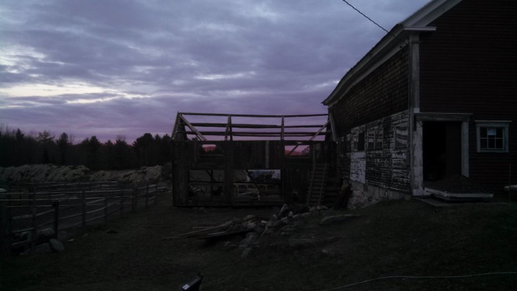
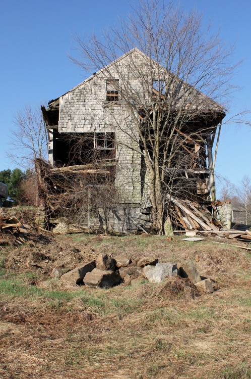
A couple months ago, Shawn and I were facing the end of an enormous barn that looked as if it had been attacked by a pair of xylophagus tyrannosaurs. The two corners posts, and the sheathing around them, were absent, and the large triangle of the gable end teetered on a center post, which was significantly supported by a neighboring tree. The ends of the tie beam had rotted off just enough to disconnect from the eave plates, but not so much that their weight was reduced.
Interior frame
The framing of the barn is unique. A center drive post extends to the ridge, and is connected to the left eave by a tie beam. On the right, a strut rises to the right rafter, and the right rafter heel joins directly with the top of the right post. This gives the barn an incredibly high drive on the right side. The client wanted to repair the entire barn, but due to financial concerns, and the fact that the gable end was disintegrating before our eyes, we decided to sacrifice the last gable bent. If the condition of the last bent is cautionary tale about the consequences of roof leaks, the condition of the rest of the bents is a testament to good timber framing. Above the deck, the frame is in remarkably good condition; below the deck is frankly a little scary, and we will be stabilizing there next.
Gable triangle, afloat
The challenge was to disengage the gable end from the roof, without allowing it to crash into the barn, and to do that, we used the lull, man lift and chain saw to great effect. A man lift allowed us to stay above the fray, and carry the purlins and roof sheathing to the pile on the ground. Once the plate, purlins and roofing in the last bay were removed, the gable end was composed of a center post, braces, a tie beam and two rafters. The rafter-tie beam connection was completed rotted through. The stability of this limited framing in a stiff breeze is a testament to braced joinery. We were able to cut the rafters into pieces above the floating gable end tie beam, and then chop the center gable post into pieces from the top down.
Scribe line, 2 ft below the plate; the details afforded by man lift access
This job challenged my perceptions of preservation and the kinds of work I enjoy. This barn will serve as a good example of a preservation through triage and we were able to save an interesting structure for a client who had limited funds. I learned that big machines can be as attuned to their task as a hand plane, and just as fun on a sunny day.
Dave, carefully removing sheathing from the Demeritt-O’Kane House
PTF’s own David Ewing will present his paper, “Moving Historic Properties: A Valid Method of Preservation” at the National Trust for Preservation’s 2013 Conference in Indianapolis, IN. Inspired by his experience dismantling the Demeritt-O’Kane house, the paper reviews the history of moving buildings and includes the example of a Boston apartment building which was moved at the rate of one inch per minute. The move took three months, and the apartments were inhabited continuously. He argues that the threat of demolition makes careful dis-assembly or intact movement a viable option for preservationists, as well as environmentalists. From the abstract:
The practice of Historic Preservation fundamentally involves the response to threatened historic places, buildings, or properties. Those involved in this professional field have the responsibility to use whatever means necessary to successfully thwart the deterioration or demolition of historic structures. For that reason preservationists must consider the merit of all potential methods. This paper investigates the evolution of building relocation as a method of protecting the resources found in the built environment. Furthermore, it explores the technological advances in the practice of relocation, the restrictive guidelines of National Registration Criteria and environmental implications in a thorough understanding of how relocation is a worthy option in the preservation of historic places.
Dave will participate in a panel discussion on “Re-Booting Preservation for New Audiences.” He is pursuing a Masters of Design Studies (MDS) in Historic Preservation at the Boston Architectural College, and his paper was selected competitively from a pool of preservationists from around the country. Dave joined PTF after a summer internship through Maine Preservation, which PTF supports as a way to give preservation professionals headed for the office some time in the field. We persuaded Dave to stay out in the field with us a little longer, and this paper is evidence that he’ll keep a boot in both environments.
Dave, removing floor joists at the end of a long day
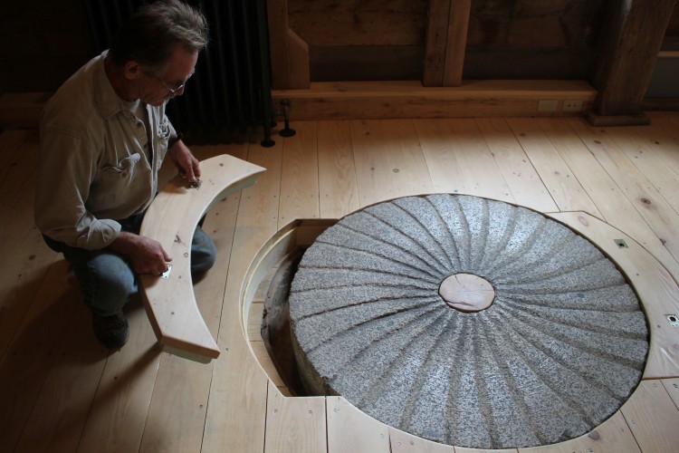
Chuck pulls up the access hatch and examines a millstone
If you grew up in Freedom, ME you’ve probably already toured the Freedom Mill, in high school, under the cover of darkness, at risk to life and limb. At its height during the 19th century, the mill had served as an economic engine for the area, using the water power at Freedom Falls to process grain and manufacture wooden dowels. By the 21st century, the mill was filled with piles of rotting sawdust, and teenagers who had nothing better to do and a misplaced trust in the floor framing. In 2011, Tony and Sally Grassi bought the property, seeing in the detritus an opportunity to preserve an historic landmark while stimulating the local economy.
Jesse Turgeon’s first post fix
The mill’s place in Maine’s history made this restoration especially meaningful for the crew at PTF. Our work places us within the long history of New England building craft, which includes its water-powered mills and early industry. PTF’s Northern Contingent had the pleasure of touring the nearly finished mill last week. A restaurant and an independent school are moving in. What the renovated mill now lacks in mischief and sheer danger, it makes up for by interpreting the industrial history of Maine, and creating a space for people to incorporate that history into their daily lives. We recommend heading up and taking a tour, before classes begin.
Foundations, old and new
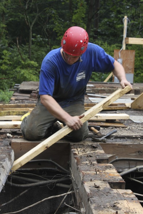
Repairing the frame posed a number of unique challenges. The undercarriage needed full replacement, and because the mill was water-powered, it was built more than sixteen feet above a rushing stream. The crew rebuilt the undercarriage exactly as it was originally framed, threading 12″ x 16″ x 22′ joists through the building and over a complicated network of staging.
Scott marvels at the massive floor framing
In addition to the exposed wall framing and the antique mill-works hanging from the ceiling, view hatches throughout the building allow visitors to discover how the building functioned as an industrial space. In the main space, a hatch allows visitors to get a close look at an old mill wheel (see first photo, above). In the main entrance, the dowel drying racks were preserved, and a viewing window shows the series of radiator pipes over which they were built.
Lee points out a detail of the mill works
A small school is moving into one of the upper floors of the mill, the exposed framing surrounding the classroom and steeping students in their heritage. It is on these upper levels where the brace repairs are best observed, right at eye level.
Marriage Marks
The crew also dismantled, repaired and rebuilt an original ell addition. The roof framing is visible as students climb the stairs to their classroom, and in the commercial kitchen.
Preserved framing in rebuilt ell
Over lunch, we saw but a small slice of the work that has been completed at Freedom Mill. The Grassi’s website offers a lot more information on the history, the restoration, and opportunities to visit. It stands out among restoration-project-websites in its simple design and readability.
Shawn, showing his pin extraction method. Photos by author
Yesterday we began the dismantling the Marrett House panels in order to repair the broken stiles and rails. Above, Shawn shows his method for extracting the pins. He drills a tiny hole through the center of the pin, then threads a screw into the hole until it just bites, and then uses a hammer claw and a lot of padding to pry the pin out. This method prevents the blowout and denting that might occur from trying to knock the pin all the way through the joint.
Wedging the underside of the joint to avoid denting the wood.
Unbelievably tight joinery made the dismantling process both frustrating and inspiring. We softly tapped a handful of soft-wood wedges into the backside of the joint between stile and rail, and checked again and again to make sure that there were no pins or tiny nails or frass creating the unholy friction that prevented the stile from moving more than 1/32 per tap.
Panel Joinery, with end stile finally removed
Once we got the stile off, we thought we’d find a fox wedge, but there was none, just incredibly tight joinery, and stunning coping. The interior edge of stiles and rails are decorated with a thumbnail profile, and the thumbnails are coped to one another rather than mitered. Coping is the process by which the negative profile of one molding is cut into the backside of another. Good carpenters cope crown and other moldings when they meet at right angles to one another so that when the joint moves with humidity changes, the molding beneath the cope is revealed, rather than a gap. Some carpenters do it better than others, and this guy was among the neatest I have seen.
Coping detail, stile to rail
I took a lot of photos of the process; click on the slideshow below for more.
When I embarked upon a career in wood, I wondered whether I should become a furniture-maker, and construct finely joined objects of beauty, or build houses, which provide a lot more utility to people. I soon found that it was a false dichotomy; working in preservation, I can work on buildings that are constructed like furniture. On the building we’ve been referring to as “The O’Kane House,” I’ve written previously on the finely-proportioned trim, and the stoutly-joined frame. Even the sheathing is weather-joined, creating a water-tight envelope, and the windowsills are grooved on the bottom to sit down tight over the sheathing. The carpentry employed at O’Kane isn’t ostentatious, but every day I am inspired by the craftsmanship employed at each phase of its building.
Given this gushing, we think that carpenter deserves some credit. “The O’Kane House” is a bit of a misnomer. For a long time, the building UNH now calls the O’Kane House was referred to as “The Demeritt House” in reference to the Demeritt family who built it, and lived on the land for more than 200 years.
In July of 2001, Jim Garvin*, the New Hampshire state historian, wrote an Individual Inventory for the NH Division of Historical Resources for the Demeritt House, one of the steps for applying for its placement on the National Register of Historic Places. In reading the report, I expected a bureaucratic list of dry historical attributes, but discovered instead a well-crafted narrative exploring the house’s former residents and their relationship to its architectural significance. I encourage anyone who has been interested in the O’Kane House to read the whole report, here.
The house was built for Israel Demeritt in 1808, on land that had been granted to his Great-grandfather, Eli Demeritt, before 1700. Israel inherited the land from his father, Captain Samuel Demeritt, and replaced his father’s two story house with the one we so recently dismantled. It was likely built by his brother Nathaniel Demeritt (1751-1827), a joiner who is known to have built a neighboring house with his son, the Rev. William Demeritt in 1819.
If Nathaniel was indeed the builder, there were architectural consequences. First of all, by 1808, Nathaniel would have been 57 years old, which explains why the house is so conservative in its layout and plan. The center chimney and first floor layout resembles other houses that began to appear in coastal Maine and New Hampshire shortly after 1700 (pg. 98 A Building History of Northern New England).
Floor Plan, two-room deep house, from A Building History…, by James Garvin
Conversely, the interior trim is far more contemporary and heavily influenced by Asher Benjamin. The casings in the front entry are elaborate, and Garvin’s report cites Plate 1 of The Country Builder’s Assistant and Plate 11 of The American Builder’s Companion as possible influences. I found a couple other possibilities in my copy of The American Builder’s Companion: in the top left corner of Plate 27 of is an example of a cornice that is very similar to the crown in the second floor front hall, and Plate 35 illustrates an example of reeding similar to that found in the Blue Chamber. I don’t own a copy of the Country Builder’s Assistant, but Nathaniel Demeritt did! His name is written in a second edition housed at the New Hampshire Historical Society in Concord. Concord readers (Hi, Mom and Dad!) go check it out.
First Floor, Demeritt-O'Kane House
Nathaniel Demeritt’s age and life experience determined the design of his brother’s house. His commitment to traditional techniques determined that the house was stoutly built, but his openness to Asher Benjamin’s new forms and proportions allowed him to trim it out in a style that was lasting. People often ask me to define “preservation carpentry” and my stock answer cites our use of traditional joinery and appropriate techniques. I mention that as Preservation Carpenters, we still get to work on houses (and barns, and steeples) that are built like furniture, which is something that can’t often be said of contemporary buildings. But one of the best parts of preservation, and something that I have tried to express through the O’Kane Notebook posts, is the connection to builders like Nathaniel Demeritt. He faced so many of the choices and challenges we still face today, and it is satisfying to uncover tangible examples of his decisions in the Demeritt House. Demeritt relied upon proven tradition to help him design a sturdy, lasting frame, and watertight sheathing, but he also made room for innovation, and style, and took inspiration from the pages of Asher Benjamin’s books. In rebuilding the Demeritt House, we will face a similar dilemma. We have committed ourselves to using traditional techniques to repair and rebuild the remaining 85% of original material, but we face choices with regard to those couple of rooms that contained no original material, and will be needed for modern conveniences. We can only hope that we will be as successful as Nathaniel Demeritt in building new rooms of lasting style.