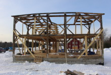
The East Derry crew has been hard at work completely rebuilding the belfry, lantern and upper lantern. The framing is complicated, and heavy. Each lantern is a separate, eight-sided tier, connected by a sweeping skirt roof. Below the lanterns, the belfry may only have four sides, but the bell itself is supported on a hip-roof floor made out of woven grid of 12″ x 12″ oak. The entire frame needed to be rebuilt. We used white oak, the same species as the original; it clocks in at about 83 pounds per cubic foot.
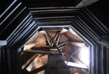
Stacked sweep. Photo by author
PTF specializes in traditional, in-kind repairs, which means we replicate the original design in the original species. While we believe in preservation, we make our decisions based on evidence. It is hard to argue with a design that has lasted 200 years. The sweep roof between the upper and lower lantern is one exception. Originally built out of stacked 2″ thick dimensional lumber, it certainly wasn’t constructed 200 years ago. The flashing failed, resulting in the catastrophic destruction of the framing below (next week on PTF blog – a whole host of hollow posts).
Dave applies the original torus trim to the sweep. Photo by Brian Cox
We carefully documented the sweep’s dimensions and radius, and constructed a new roof using radiused rafters. The resulting roof is precisely the same shape, but lighter, stronger and less susceptible to moisture infiltration. Above, Dave returns the original torus molding to the newly framed roof. It is hard enough getting miter joints to close on a four-sided building, and much harder at eight. The torus joints came together like they were going home, evidence that the crew achieved an exact replica.
Have you ever seen such gorgeous sheathing? Photo by Brian Cox
The upper lantern was completely assembled at our shop in Nottingham. It will be clad in wide Eastern White Pine, sourced locally, and trimmed in African Mahogany, which was a concession to the species’ superior consistency in milling, and comparable weather resistance. The sides were preassembled in panels and then removed so that the siding can be applied over the copper flashing at the connection with the sweeping roof.
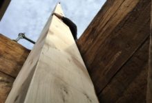
Wedding topper. Photo by Brian Cox
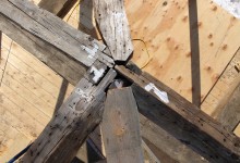
The lantern is roofed with an octagonal wedding cake, which is penetrated by a mast that extends through the center of the frame and lands on the lower lantern’s bed timbers. The mast was originally scarfed together from three timbers. We reproduced that design, which will ease the assembly process and transport to the copper shop. The original lapped scarf is visible in the photo of the stacked roof.
Soldering the skirt. Photo by Brian Cox
In his report, Arron noted, “The sweeping roof is perhaps the most important roof on the entire tower. It is here that poor roofing allowed water to penetrate into the center of the tower and rot both the upper and lower lantern frames.” At the Heritage Company, in Waterboro, ME, Victor Wright and his crew redesigned the flashing details to ensure that they will be impervious to weather.
Up next week: the consequences of poor flashing, and reproducing the lower lantern frame.
This blog leaves a lot out. We can’t give our projects their full due here while giving them their full due out there. I’ve been especially remiss with regards to East Derry. The First Parish Project has been in progress since 2012 and includes the replacement of the undercarriage, moving the building onto a new foundation and rebuilding a belfry, lantern and spire. In the video above, we are replacing two continuous 60 foot posts in the standing tower. There was a lot of back and forth about dismantling the tower, but ultimately, we left it up because housed inside are the intricate mechanics of a historic pipe organ. Reassembly of the organ rivaled reassembly of the tower for level of complexity and expense. While we’ve been remiss in coverage of this long hard road, Paul Lindemann, a dedicated leader of the building committee, has been documenting the process on his website: Nutfield History. Paul made this sweet time-lapse video of the posts being inserted. The video may condense the day into just over a minute, but the installation of these posts was the culmination of months of documentation, design, demolition and rigging. In order to stabilize the building, the crew essentially built a skeleton tower inside the existing tower. It was big. The entire crew should be commended for their hard work, determination and fortitude, but especially Brian Cox, Dave Ewing, Dan Boyle, Tom Glynn and Seth.
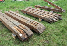
It just so happens that the crew is delivering the belfry frame to the church today. Each of the full length belfry rafters are 12″x 12″x 14′ and weigh in at around 1200 lbs. We’ll keep you posted.
For me, it was not love at first sight. The Dummer House, built in 1786, is the oldest in Hallowell. Tucked onto Dummer Lane, the building had already been moved once and was languishing under a pair of overgrown maples, awash in eau du restaurant dumpster. It’s a plank frame building, which means that the 2 inch thick sheathing performs structurally. There are corner and intermediate posts, but no studs. Back when I was a student of preservation carpentry at NBSS, my instructor introduced us to this rare frame style with a not-quite joke: “If you ever get the chance to buy a plank frame house,” he said, “Don’t.”
Plank frames are notoriously difficult to repair. The lack of sheathing means that there is one less barrier between the elements and the frame, and fewer framing members to support the building during stabilization. If the sheathing separates from the sills, the entire wall can fall away from the building, and that’s what I’d seen on my one previous visit to a plank frame. My prejudice was getting the better of me.
Last summer, the Dummer House was moved again, by Geddes Building Movers. After three stress-free moves with the company this summer, we are crushing hard. They do the work of easy-going giants, gently lifting the building onto steel I-beams and rolling it into position using rugged rotating skates. The Kennebec Journal made this sweet time lapse of the move (dear reader, support your local news!)
Dummer House, after
When I returned this fall, the building had been turned 180 degrees and moved uphill to face Second Street at the intersection with Center. The spin returned the house to its original relationship to the street, so that the paired doors leading to the front hall are steps off of the sidewalk. No longer hidden by the brick buildings on Water street, the historic features of the Dummer House make an impression. The historic significance of the building can be better appreciated in an appropriate context with its front and side streets. In back, the building stands a story above a new municipal parking lot. And even this ahistorical view is an improvement. Looking up at the building from the parking lot, I fell in love.
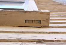
Plank frame window pin
After the entrance, windows are the defining aspect of a building’s aesthetic. Their presence or absence and location communicate building use and place it in a historical context. For this reason, windows are frequently replaced when a building is “updated”. Looking at old buildings, it’s rare to find the original windows, and especially rare to find original sash or glass. Whenever I visit an 18th century building, I look at the ends of the windowsills in search of the shadow of a wooden pin behind the thick paint. The pin indicates the mortise and tenon joint at the heart of plank frame window construction. Rarely am I lucky enough to see the pin, much less the joint itself.
Plank frame window tenon
From the parking lot behind the Dummer House, a visitor can see the underside of the windowsills and the ends of tenons poking through – be still my beating heart! Instead of falling away from the sills, the walls have retained many of their original adornments: front entrance, clapboards, and plank frame windows. In a contemporary window, the frame is constructed from a hollow, 3-sided post. Three 3/4″ thick boards are rabbeted, nailed, and glued into a C-shape and make up the interior casing, the jamb and the exterior casing. In a plank frame window, the frame is constructed from stout timbers, about 3-4″ wide and 4-6″ deep. Because the jamb is solid, the front casing is the dressed front edge of the jamb. The jambs are joined to the hefty header and windowsill by a mortise and tenon joint. Seeing the end grain of those tenons poking through the bottom of the sill warmed the cockles of my heart.
In the winter, we hope to begin restoring the house, which will serve as a historic house museum. First, the undercarriage needs to be completely rebuilt, so we’ll get practice in rigging a plank frame building. Restoring the plank frame windows will come later; we’re lucky they’re still there. If you’re thinking of replacing your old or original windows, think twice. A restored window, with interior and exterior storms, can perform as well as a triple glazed window. Vinyl windows are almost impossible to restore (why bother?) and start to sag in a few years. If you’re interested in a turn-of-the-century wood window restoration, read more here.
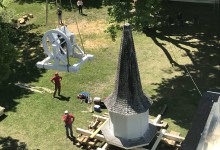
The last bell to leave the Revere Foundry leaves its perch. Photo by Scott Lewis
It is never a pleasure to break the news that a steeple should be removed to ground. It usually indicates a catastrophic level of deterioration and a total budget in six figures. We only make the recommendation when it is the best approach and the most economical. We remove a steeple when it is the most assured path to its restoration. These steeples define Maine’s skyline. They are one of the most important characteristics of New England’s shared architectural heritage. Every time, we worry that the steeple won’t be returned to its perch, but frequently, removal is one of the best fundraising motivators. Removing a steeple to the ground makes the job safer, it reduces staging costs. It allows us to preserve more original material. Usually, due to underlying frame damage, it isn’t just the best option, its the only option.
It’s a sad day when a steeple is removed, but it’s exciting too. The whole crew is on site, along with a big crane. The rigging is a fascinating geometric puzzle and the removal sequence is a high-wire choreographed dance. This summer, we removed two such steeples, at Benton Falls and West Auburn.
Benton Falls Congregational Church
During my first assessment visit to Benton Falls, I squeezed through a hatch in the tower roof and emerged beneath the bell cradle, banging my helmet on the last bell ever to leave the Revere Bell Foundry. On my second visit, a few months later, no amount of beating would open that hatch. The tower plates were nearly non-existent, and Paul Revere’s last bell was slowly crushing through the roof.
In the architectural glossary of my mind, Benton Falls illustrates “adorable”. This is from our original existing conditions assessment:
Built in 1828, the Benton Falls Church is understated and intimate; it is embellished just enough to fit in with its surroundings, but not make a statement of its austerity. An archetypal rural Maine church, the gable-roofed main building is 38’ x 42’, with a 12’ x 12’ tower resting on the front gable wall and first interior bent. The tower is topped by an open, octagonal colonnade, notable for containing the last bell cast by the (Paul) Revere Bell Foundry in Canton, MA. The belfry is topped by a simple lantern and well-proportioned, eight-sided spire.
Overall, the building is showing its age, alongside a history of committed Yankee maintenance.
Belfry columns, stacked on ground. Photo by Scott Lewis
A few of the turned belfry columns were rotting, and would need to be extracted from the building. The turned portion of the column was only about half its length. The bottom half is a timber blank that telescopes deeply into the building and lands on a catty corner crab 8 feet below.
Rigging stack and crab hashtag.
We were not able to access the lantern and spire framing on our assessment visits, but the witch’s hat needed to be removed based on the condition of the belfry posts and tower roof alone. Standing on the tower roof, and tied into the framing, the crew re-enforced the lantern crab with a triple-stacked grid of KD (kiln-dried 2×10). Then they assembled rigging timbers by laminating together four layers of 2×12. The rigging timbers were stacked on edge, and crossed like a hashtag. They extended past the lantern by half its width. Eight rigging straps choked the ends of the rigging timbers, and were hung from a square steeple cage.
Lantern crab center
The local CBS station, WABI 5, caught the crew rigging the steeple on crane day. The tv crew interviewed members of the congregation and neighbors about the importance of the church in their community. Congregants expressed their commitment to preserve the building with traditional in-kind repairs alongside the challenges of fundraising. By partnering with local craftspeople, we are able to cut costs, increase efficiency and share our knowledge, but these projects are expensive, especially for a small congregation. There are those who will promise they can do the job more cheaply. Unfortunately, it is cheap repairs, devoid of joinery and overly reliant on steel, that we are most frequently called upon to re-repair, twenty years later. There’s no fiberglass steeple that has lasted as long as a timber one.
Lantern crab, mast and strap
On the ground, we’ll be able to repair the belfry posts, and document the beautifully crafted spire. It has not one, but two gods-eye shaped crabs, one for the lantern, and another for the steeple, which is supported by a central mast. The crab and mast are secured with a wrought iron stirrup, pinned and wedged. Consistent with its age, the builders used a little bit of iron in the right places: to reinforce joinery at the crab’s center and at the ends of the trusses, preventing the rafter heels from blowing out their mortises.
Spire crab and mast
Benton Falls is currently raising money to restore their steeple, you can reach them on Facebook, where they also have a video of the steeple flying.
West Auburn’s steeple was also removed this summer, using a similar rigging system. Both churches accessed the Maine Steeples Fund to help with assessment and repair costs. West Auburn got attention from the Sun Journal and NBC’s NewsCenter Maine. You can visit them on Facebook, too, where you can see photos of their steeple flying.
To the crew at least, the most impressive piece of the French frame is the roof system. The roof has a very low pitch: the apex of the ridge is little more than 4′ above the tie beams. There are two continuous ridges, each about 30′ in length, that meet on top of a short mast at the center of the crotch of the L. Each hip-roofed end also has mast resting on a mid-span tie beam, which catches the rugged hip rafters. Each full length tie beam is topped by a pair of principal rafters which tenon into the ridge beam.
Plate installation with Jake and Scott. Photo by Timothy Sweeney
The tops of the posts are ringed by a set of co-planar plates, joined to one another by mortise and tenon. There is 38′ plate along the south eave and a 36′ plate along the west eave. There is another full-length plate along the north eave connecting the east gable to the west eave. At the inside corner, where the valley collected rainwater, and where an interior post was removed or missing, the north eave plate failed, and required a long double-scarf repair (being assembled, above). For this house, we used plate to refer to the gable end timber that tops the studs and connects the corner posts. To create hip construction, this beam itself is crossed by a set of tie beams.
Foley Roof Frame
The tie beams cross over the plates using a partial half dovetail joint and overlap the plate to a depth of 3″. There are four full length tie beams in the main portion of the building and five full length ties in the ell. The ties closest to the gable are about nine feet from the end of the building. Two short tie beams cross the gable end plates and join the full length tie beam with a pinned mortise and tenon joint. A hip, or dragon, tie extends diagonally from the short tie and clasps the plate joint at the corner.
Hip tie clasps plate joint.
Each tie type is topped by a distinctive rafter. The full length tie is topped by a pair of principal rafters, which tenon into the end of the tie beam. The hip tie is topped by a hip rafter, and the short tie is topped by a jack rafter, which joins the hip rafter at a compound angle and full mortise and tenon joint. Zach had fun scribing one of these babies.
Masts in the Grass
A short four-foot mast supports the apex of the roof, receiving the end of the ridge, two principal rafters and two hip rafters. When we were inventorying the frame, the mast joinery looked rough, like it had been hacked with an axe. There was no consistency to the cuts, and no way to accurately model the joinery. When the frame was in parts, we weren’t crowing about the original builder.
Jake installs a jack rafter
We assembled the frame using a lull, dead men and muscles. Considering the inconsistency of the bents, and the complications of the second floor, hiring a crane wasn’t efficient. Using a crane on-site for more than one day is a huge investment, and more than two days was beyond the scope or need for this project. So the raising was incremental, and slow.
Raising in progress. Photo by Timothy Sweeney
We waited to assemble the roof parts until after the rest of the frame was raised. There was no advantage to fitting the parts on the ground. We had almost all the original roof framing, and we were going to sheath the second floor as soon as it was raised, providing us with a contiguous deck on which to roll staging. When we finally placed the first roof timber, we were more than a year into the project.
Scott fits rafters to mast
Where assembling the house frame was frustrating, assembling the principal roof frame was gratifying. The original principals landed on the original masts like they were going home. The ugly axe cuts at the top of the mast were beautifully scribed to the undersides of the hip rafters. In modeling the roof frame, we could tell that the design was complex, but until we fit the pieces together, we had no idea that it was also beautifully crafted. It inspiring to witness, and to contribute our skills to its repair.
Two ridges, three rafters, one mast. Photo by Timothy Sweeney
This is the third post in a series about the Foley-French House. Check out more in progress photos, here, or by clicking on the slideshow below. If any of the photos look professional, but they don’t say “by Tim”, I forgot to credit Tim. Next up, scarf joints.
French House, c. 1804. Kingston, NH, Front Elevation. Photo by Charles Foley
If you are prone to feeling lazy, you’ll have to ignore the Foleys. In addition to their intense day jobs, they care for four horses, a flock of sheep, chickens, and a pack of wild dogs (it’s only two dogs, but they have a lot of energy). The French frame is the third frame we’ve raised on their farm and they finish the projects after sheathing. Sheila dug the footers for the solar array herself. At the outset of our most recent project, the couple was so involved in the design process that it wasn’t really a PTF design job at all. And that worked well for us. I’m happy as a draftsperson.
The French Frame, built in 1804, is L-shaped, two stories, hip-roofed, and always has been. It was also remarkably intact for two centuries of adaptation and use. The posts are tapered gunstocks and varied widely in dimension. Each leg of the L is 18′ wide; the front eave is 38′ long and left eave was 36′ long. The house was built with three full length plates – front (south) eave, rear (north) eave and left (west) eave – but the rear plate was damaged at the rear interior corner, and required a long scarf repair. Assembling the plates made us wonder at how they did it without a combustion engine. We added three bents off the rear (north) end of the ell, bringing its overall length to 68′. We also added an additional bent between the two original ell bents because 18′ is way too long a span for contemporary floor load requirements.
French House, Left Elevation. Photo by Charles Foley
PTF came aboard after the frame had been dismantled in Kingston, NH, transported, and stacked into temporary quonset huts in Poland, ME. I described our process for deciphering the frame here and a little bit here. Our first day back on site we inventoried and assessed the frame’s condition and I drew a 3D model using SketchUp. There are a number of other 3D modeling programs used by design professionals, but SketchUp has so far been best at meeting our timber framing needs. The next time I approach a project like this, I will model each timber to its exact specifications from the get-go. This will make it harder to establish the building’s overall dimensions initially, because hewn timbers vary and joints loosen, but it would negate the need to go back and make tedious changes to the model at cutting time.
Tie Level Hip framing
It’s not always a pleasure to work with a client who wants to share the work load. Scheduling can be a challenge. The arrangement requires both a clear delineation of tasks and flexibility to address problems as they arise. We have been lucky in our partnerships, but in this case, the design collaboration was ideal. Charley had a very specific vision and was able to convey it using an iPad floor plan app, in addition to teaching himself a little SketchUp. He has strong preservation aesthetic, and wanted to preserve the building’s original elevations and roof overhangs as close as possible within the bounds of modern building codes.
Simplified First Floor Plan
The Foleys retained a traditional floor plan within the original frame, and sequestered newer elements to the three bent extension off the ell. The building has a center stair layout with a chimney stack is built into either end of the main body of the building and a fireplace on each floor. In the ell, a third chimney mass is the focal point of the kitchen, with a traditional cooking hearth and beehive oven. George Libby of G.M.Libby and sons masonry designed the chimneys and provided guidance on their integration within the frame. The company specializes in traditional masonry and we have been very impressed with their work on previous jobs.
In contrast with a house museum, a house needs to meet contemporary building codes even if it is trying to maintain NPS-level standards. Balancing insulation requirements within a traditional frame is always a challenge. Usually, the client must decide between building out and building in. Building out means that an insulating exterior skin will be applied to frame like with SIPs or shop-made insulated panels. The advantage of building out is that the frame is visible to the interior. The disadvantage with a traditional frame is the exterior no longer resembles its original proportions. For our shop in Berwick, Arron chose to insulate to the outside, using a shop-made sandwich of pine shiplap and denim insulated batts. He achieved a fairly traditional look, but the walls are certainly thicker than the original barn wore. For this project, the Foleys wanted to insulate to the interior, and retain views of frame to the extent possible. This results in elevations that are much more true to the original building. At the first floor level, the clients will see the interior face of many of the posts and more timber in the second floor framing than the 2013 pop charts. On the second floor, the impressive tie and dragon beam configuration will be visible as well as most of the posts where they flare to meet the tie beams. Unfortunately, insulating to the inside will obscure the principal rafters. In most of Maine, code requires R-49 in the roof, resulting in 13.25″ of the preferred insulation, Roxul batts.
Y-stair section, simple-style
Fitting stairs is always the other big squeeze. In many buildings of this age, stair rise is taller than run is long. An 9″ rise and 8″ run is not uncommon. At my in-laws house from 1840, my size-tens ascend the stairs sideways, like a crab doing the grapevine. In order to approach the original layout of the French house, the front stair rises directly from the main entrance and doglegs to the left. The rear stair behind the beehive oven was my favorite design challenge. It was similarly limited by an overall 18′ run, with 3′ landings, minimum, on either end. Due to the second floor plan, the rear stair is Y-shaped, leading left to the master bedroom and right to a hallway that accesses the bath and music rooms. The master bedroom is private, being sequestered from the second floor family space, and accessible from the kitchen and frequently used rear entrance.
South Elevation, just the basics
For fenestration, we followed traditional lite divisions and window proportions. We selected the largest lite size commonly found in Federal-era windows in order to accommodate fire egress required for the bedrooms and to maintain a consistent window size throughout. The clients ultimately chose a wood window manufacturer to contain the cost over custom wooden sash. Although we didn’t use them here, there are a number of competitive sash manufacturers in New England if traditional sash is your priority.
Second Floor Framing, just the sticks
Once the floor plan and fenestration was established, we hired an engineer to review the framing plans. Due to the 17′ open span across the first floor and the spans between bents, this resulted in gargantuan floor girts, 10″x12″ and 12″x12″ in cross section. Big timbers can be fun to find in an original frame, but these seemed out of proportion with the rest of the frame. And then we didn’t even hear a peep from the code enforcement officer. It was both good fortune and a little disappointing that he wasn’t more concerned.
Jake and the Big Floor Girt. Photo by Timothy Sweeney
It’s been more than six years since fate matched up Charley and Arron at a decrepit barn in West Poland, ME. The teenager who chauffeured Arron that day, in preparation for his driver’s license, is graduating college in May. Since then, we’ve stabilized a dairy barn, moved a carpenter’s shop, and erected a horse barn just in time for Charley’s wedding. There is something specifically rewarding about collaborating on a home for such long-standing clients. We get to bask in the glow of our friends achieving a dream.
Foley Frame in February
Next up, scarf repairs and some exquisite hip joints.
Almost a year ago, we faced the year’s first pile of pick-up sticks: a neat but undifferentiated pile of timbers that formerly formed the French House of Kingston, NH. They were first assembled in 1804, around the time that the landmark Badger Tavern opened in Kingston, and the formerly enslaved overthrew their oppressors in the Haitian Revolution. More than two centuries later, the house was dismantled and transported to the Foley property in Poland, ME. It will soon become the home of two of our most steadfast clients, Charles and Sheila Foley.
Initially, at least, the project was like the Reverend Morrison House; we were charged with deciphering the frame and drawing a model, but the projects diverge dramatically from there. While the Morrison House will ultimately be interpreted for the public as a historic house museum, the French House will include four new bents off the back ell and indoor plumbing. The ultimate aesthetic will be historically accurate, but the home will be comfortable for a 21st century family.
Foley House Posts
Typically, PTF models the building and establishes tagging numbers before we dismantle. It is easier to determine the overall dimensions of a building while it is standing than when it is in parts. Tagging each member with an individual tagging number makes it easier to identify and inventory the pieces after they have been moved to the new site. The dismantlers of the French house used what is actually a more traditional method. They numbered the posts 1-10, and painted the associated numbers on the intersecting plates, tie beams and girts. The approach resembles trail systems that number the intersections of trails rather than naming the trails individually. Occasionally, we encounter old frames whose marriage marks have been numbered in this method, albeit with chisels and roman numerals rather than white paint. Ultimately, deciphering the members of the French House was easier than the process at Reverend Morrison, because the framing members were smaller, better organized, and more complete.
Foley House Rafters
The Foley house is L-shaped and always has been. Three of the plates are continuous, or were originally at least, and are almost 40′ long. It is unusual to find a two-story home from the Federal Period with an original two-story ell. The two 40′ plates, and two continuous ridge beams join one another, making it difficult to imagine how the building was originally assembled. The roof is an impressive feat of joinery, with three low-pitched hips. Given its distinctive roof structure, maybe the house is more accurately situated in the late Georgian period. Go ask Virginia McAlester.
Foley House Plates
The continuous plates were essential to deciphering the organization of the frame. Due to their length, they were stored separately in the loft of the horse barn, a project we’d reassembled one year prior. Post locations were labelled with the appropriate number in white paint. Each leg of the ell contained two additional tie beams, located in between bents. Each end of the extra tie beam and the associated half dovetail mortise in the plate was labelled with a symbol, rather than an alphanumeric. It was easy to identify the tie beams by their size, the half dovetail joinery on either end, and the long rafter mortise above the half dove. For more about identifying timbers based on joinery alone, see Salvage Detectives, part 2. Fortunately, the continuous plates in this frame provided us with the tie beam layout. If you ever find yourself facing a pile of frame with no map, find the plates and the tie beams. They provide the most accurate overall dimensions and a map of the bents, such as they exist.
Foley House Posts, gunstock profiles
From both aesthetic and historical perspectives, a fully scribed and hewn frame is desirable. In the case of the French House, it also means that the dimensions of the timbers are wildly divergent. There was no uniformity to the posts or eave girts. In older 18th century hewn frames, the girts will be oversized and the joists will be undersized, reflecting the size of the tree from which they were hewn. Hewing is labor-intensive, and frequently, the hewer would stop once he achieved flat and square faces. In this house, the scribing and fit of the joinery was remarkable, but the hewn surface and subsequent centuries of alterations left the timbers uneven. Initially, we documented the exact measurements of each of the pieces, in order to establish an average height from top of sill to tie beam. The length of post varied by nearly an inch. We modeled the frame using an ideal post size and established some uniformity to the girts. After the floor plan and window layout was established, I needed to go back to the framing members and adjust each post to its actual dimensions to achieve accurate girt lengths. If I could turn back time, I’d model each stick of the frame individually from the beginning, rather than revising the model later to achieve more accurate measurements needed during the cutting process. I’d also make cut drawings of each of the original timbers, regardless of whether there were significant alterations to the piece. It would allow the crew on site to double check actual measurements against the model.
Constructing the Foley house has been nearly a year-long journey. With the client, we designed a home to suit their needs and meet their historical standards. Upcoming posts will describe the design process, scarf repairs and the incredible hip roof joinery.
An enduring feature of timber frames is that they can be dismantled and re-used. A traditional barn-raising, in which a community comes together to erect a frame in one day is preceded by weeks of joiners’ labor: cutting and fitting the posts, girts and braces, plates and tie beams. With the help of many hands, or a gin pole, or a crane, a frame can be raised or dismantled in a day. The relative ease of assembly, and more importantly, disassembly, is why we sometimes find 300 year old frames in 200 year old buildings. The act of preservation and adaptive re-use is a centuries-old tradition, regardless of the age of the frame itself.
This year, engaging in this tradition has been equal parts fun and maddening. We were hired to decipher two frames tagged and disassembled by other contractors. One was the Reverend Morrison House, c. 1726, which was considered to be the oldest house in Londonderry, NH, and is being restored by the Londonderry Historical Society. The other is the French House, c. 1804, a 2-story hip-roofed house that was slated for demolition in Kingston, NH. It’s being restored by Charley and Sheila Foley, who are becoming old hands at this. Both frames were tagged before dismantling, but neither is attended by a full set of tagging drawings. We use tagging drawings like the picture on the box of a jigsaw puzzle. While we try to follow consistent tagging patterns, tagging a frame is pretty idiosyncratic. It’s unlikely that any two PTF frames would have tagging consistent enough to decipher the tags without drawings. That’s what made deciphering these frames such a…fun-show.
SST7 and its old friend, Tom
The Rev. Morrison House was dismantled with tags similar to our own. Alphanumeric codes identified the location of the piece, the type of framing member, and its number in a sequence. We could tell, based on timber size, and the half dovetail at its end, that SST1-SST7 were tie beams. But was SST1 at the outside wall of the west ell, at the west gable, or at the east gable? And what did SS mean? That one remains a mystery.
South eave, prior to dismantling. Photo courtesy Londonderry Historical Society
Although a disassembled frame looks a little like a giant’s game of pickup sticks, it’s actually pretty easy to decipher how each timber was used. The joinery at either end of a timber communicates whether it was vertical or horizontal, and the joinery along its length tells us a lot about it’s location.
Knowing the English tying joint allows us to identify the timbers that establish the overall dimensions of the building. This joint is where the post, plate, tie beam and rafter intersect. The plate is a timber that runs parallel to the eave at the cornice and passes over the exterior half of the eave wall posts. The tie beam crosses the plate, directly over a post and directly beneath a principal rafter. Tie beams prevent the eave walls from spreading under the outward thrust of the rafters. The end of the tie beam is cut into a half dovetail, and performs a mechanical task that contemporary builders assign to metal fasteners. More about tying here, and here. The plate accepts the tie in a half-dovetail-shaped mortise. In order to secure all this framing, the post is joined to both plate and tie. It is flared at the top, sometimes in an iconic, stepped “Gunstock” shape. The interior half of the post extends vertically past the plate and terminates in a “teasel” tenon, which inserts into a mortise in the tie beam.
Tie beam end with half-dovetail and rafter mortise
We could identify tie beams by the half dovetails at either end, their size, 11″ x 11″ x 20′, and the long rafter mortise located right over the dovetail. The joinery in between will tell us whether the tie beam was located on either end of the building or across the middle. Tie Beams are located above the posts at the level of the attic floor. A tie beam from the gable end will have open cog mortises to receive attic joists along its top and interior faces. It will have closed stud mortises along its top and bottom faces towards its exterior, reference face. The reference face will most likely have a series of fastener holes left over from the sheathing. A tie beam from the middle of the building will look different. It will have cogs for attic joists along both sides. It will not have stud mortises on its top face, and it may or may not have stud mortises along the bottom, for partition walls. It was easy to tell the EPlate1 and WPlate1 were gable tie beams and the TS1 and TS2 were the interior ties. The carpenter who dismantled the building apparently considers all major beams that ring the post tops “plates” and, you know, that’s his prerogative. I guess he didn’t read this.
Tie beam end in plate pocket
Plates, as we define them, run along the eave across the tops of the posts. In older timber frames like the Rev. Morrison house, they are smaller than tie beams in section, 6″ x 11″, but longer: 30′. The Reverend Morrison House has a long shed off its north wall and a shed off its west wall, too. The north shed plate was much smaller, 5 1/2″ x 9″, but 46′ long. This little plate received the short ties SST1-SST6 in an evenly spaced series of dovetail mortises. A plate will have post mortises and stud mortises along its bottom face. In18th and early 19th century timber frames, “English” timber frames, the plates will be the longest continuous framing members.
Gunstock post tops. Plate tenon on top, teasel below
In an “English” frame, the post will be the easiest timber to identify. The Morrison house had beautifully stepped gunstock posts, 14′ 3′ long, 7 1/2″ x 9″ at the bottom and 8″ x 12 1/2″ at the top. The plate and teasel shoulders are offset from one another by two to four inches and the end tenons are oriented 90 degrees to one another. A corner post will have brace and girt mortises along two outside faces. Interior eave posts will have brace and girt mortises on opposite faces, and in a two-story building like Morrison, a second floor girt mortise on its interior face. The orientation of the stub tenon on the bottom of the corner posts will indicate how the original perimeter sills were arranged.
Perimeter girts will contain joist pockets that reveal joist orientation and joist layout. The Rev. Morrison house had an enormous chimney girt, 9″ x 14 1/2″ x 18′ 8 1/4″, and second story summer beam that connected the chimney girt and the east gable end girt, 10″ deep by 16″ across.
Saltbox west gable. Image courtesy Londonderry Historical Society
Once the timbers were identified, we were able to arrange the second and attic floors on the foundation that had been poured before the untimely death of one of the project coordinators. Just when the pieces were starting to fit together, the real mystery of this house was revealed. At the time of its dismantling, the building was a traditional saltbox shape. There were three bays, 12′, 8′ and 20′ wide, measured from reference to reference, west to east. We were told that the West bay (12′ wide) was a later addition, and the plates confirmed this.
West end of plate, upside-down
The ends of the plates were totally weird. They terminated in a sloped, stepped shoulder that we’d never before seen in so many years of investigating scarf joints. The end of the plate was long incline, that was sliced to half its width, as in a sloped, vertical lap joint. But the shape of the joinery wasn’t the weirdest thing about the plate. The weird thing was that it extended past the second bent, past the second pair of posts, by about sixteen inches. While the ends of some tie beams extend past the eave walls to create an overhang, that is a later style that was clearly not the case in this building. The overhang is not mirrored on the opposite gable end, and the ties do not overhang the eave walls. The building could not have originally ended at the current second bent, because there would have been two oddly shaped plate ends poking out of the west gable end of the building.
West end of plate, with extension in place
But the length of the plates remained a curiosity, why did they extend west, past the outside faces of the posts? Additionally, the west gable wall posts were not continuous like the posts in the rest of the building. Ultimately, we determined that there were a pair of short teaseled posts on the first floor, with their teasels facing east, towards the main building. Originally, these posts were topped with a tie beam at the second story level, running perpendicular to the gable. Later, the tie beam became a second floor girt. A second pair of posts were cut and stacked atop the first, their teasels facing one another and linked with a tie beam parallel to those in the rest of the building. A single story ell preceded the saltbox roof on the west bay. Photos from the dismantling revealed that the chimney, located in the center, 8′ bay, was built with three fireplace openings, facing East, North and West. The fireplace opening and plate length indicate that a west-end, shed-roofed ell was original to the structure. The weird sloped shoulder cut into the end of the plate originally received shed rafters.
Tie beams, early and late. Later tie beam “WPlate” is up top
Investigating the tie beams confirmed our suspicions. When the building was dismantled, the tie beam on the west gable end was labelled “WPlate.” The next tie beam in was labelled TB1. TB1 served as the west gable tie beam when the building was built around 1726. Above, WPlate and TB2, a mid-span tie beam, lay next to one another. You can see attic joist pockets in TB2, and that they are laid out evenly until they get to the chimney mass, where there is a gap in the sequence. Both tie beams are hewn, but the hewing in the upper timber is more crude, and consistent with the quality of hewing on the plate extensions. The hewing in the rest of the frame was consistent with the fine hewing of the lower timber. The later timber is still quite early, and contains a number of wrought nails. This indicates that the west bay was converted from shed roof to salt box in the first quarter of the 19th century, at the latest.
Morrison House Isos
It took us nearly a week to extract the timbers from the trailers, decipher their use and document their dimensions. We used that information, along with dismantling photographs, to create a scale 3D model in SketchUp. Using this information, the Londonderry Historical Society can restore the building, and decide the time period to which they will interpret. Ultimately, deciphering a dismantled frame is like a Times crossword puzzle, the degree of difficulty is matched by the feeling of pride and satisfaction in the solution.
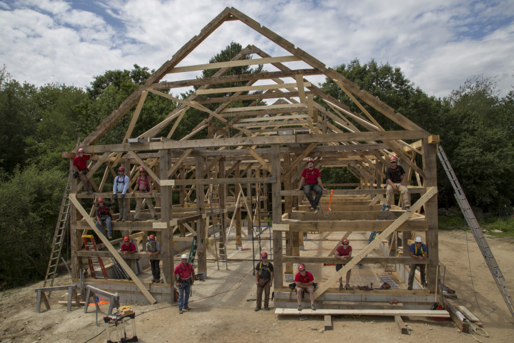
Raising the right eave wall, an 8-point pick. Photo by Josh MacNally
“We have to raise Weigand by the second cutting.” To a slicker like me, Arron was exhorting the crew to finish repairs on the enormous Brasen Hill Farm barn in time for some mysterious Pagan ritual. He was right. As soon as the roof was sheathed and papered, and before it wore metal roofing or sidewall sheathing, Eleanor Kane and Theo Weigand’s crew were loading the lofts with hay. Arron loves our collaborations with farmers and is wont to wax poetic about the symbioses between traditional buildings and sustainable farming. Partly, I think he’s in it for the work ethic farming requires.
Raising the left eave wall, and Zach lugging a girt. Photo by Josh MacNally
The barn at Brasen Hill was built in the early 1800s. It’s a hewn frame, with English tying joint and gable entry. Curiously, the seven bents were referenced as if for an eave entry, although it doesn’t appear that an eave entrance was ever installed or used. The previous owner, Randy Warren, just published a memoir: 67 Years of Stewardship, The Warren Farm, A Unique Farming Story. In it, he writes of their efforts to stabilize the barn, which was sinking into the ground. Every so often, they would jack up the “interior vertical beams,” or drive posts, and pour concrete pads underneath. One year, after they released the jacks, one post just stayed up there, and the barn proceeded to twist and settle around it. We admire his efforts. It’s hard to locate the time or funds to repair a large barn, especially a working one. That hasn’t changed. See second cutting, above.
Installing a tie beam, a 4-point pick, Photo by Josh MacNally
By the time PTF got to the project, the entire right eave was toast. Eight of fourteen rafters needed to be replaced, along with three of the seven tie beams, and more than half of the twenty-eight posts (interior and exterior vertical beams). We were grateful to the Weigands for their commitment to the barn, the craft embodied in its timbers and its centuries of service. The new barn already has garlic drying in its rafters. It houses a new insulated break room, with a poured concrete floor. It will house goats and sheep, chickens and turkeys. Maybe a cow. Brasen Hill Farm offers a sliding scale CSA from June to October and sells Christmas Trees in December. Their farm store is open now. The pictures don’t do it justice, go and visit!
Dan Boyle is serious. He means it. Photo by Josh MacNally
We bid a fond farewell to Josh MacNally this week. He left us with beautiful parting photos of the Brasen Hill raising and finished barn. Thanks for all the hard work, Josh!
Contented crew after a long crane day. Photo by Josh MacNallyBig barn from the hay loft. Photo by Josh MacNallyInterior Vertical Beam foot fix (all the drive posts got ’em). Photo by Josh MacNallyBladed scarf joint over eave post. Photo by Josh MacNallyWe installed two new staircases for better access to the lofts. Photo by Josh MacNallyA reclaimed roof system. Photo by Josh MacNallyFinished product, with three new sliding woman doors. Photo by Josh MacNally
For more photos, peruse our Flickr album. Thanks, everybody! But especially David Ewing and Dan Boyle.